Floating-ground isolated power supply for an electronic converter

a technology of floating ground and isolated power supply, which is applied in the direction of power conversion system, dc-dc conversion, pulse technique, etc., can solve the problems of expensive solution and space-consuming on the printed circuit of the board, and achieve the effect of minimizing the cost and the size of the energy conversion system

Active Publication Date: 2021-02-25
INST FR DU PETROLE
View PDF0 Cites 0 Cited by
  • Summary
  • Abstract
  • Description
  • Claims
  • Application Information

AI Technical Summary

Benefits of technology

[0009]The present invention provides an isolated power supply for

Problems solved by technology

This solution is often expensive and space-c

Method used


Image

  • Floating-ground isolated power supply  for an electronic converter
  • Floating-ground isolated power supply  for an electronic converter

Examples


Embodiment Construction

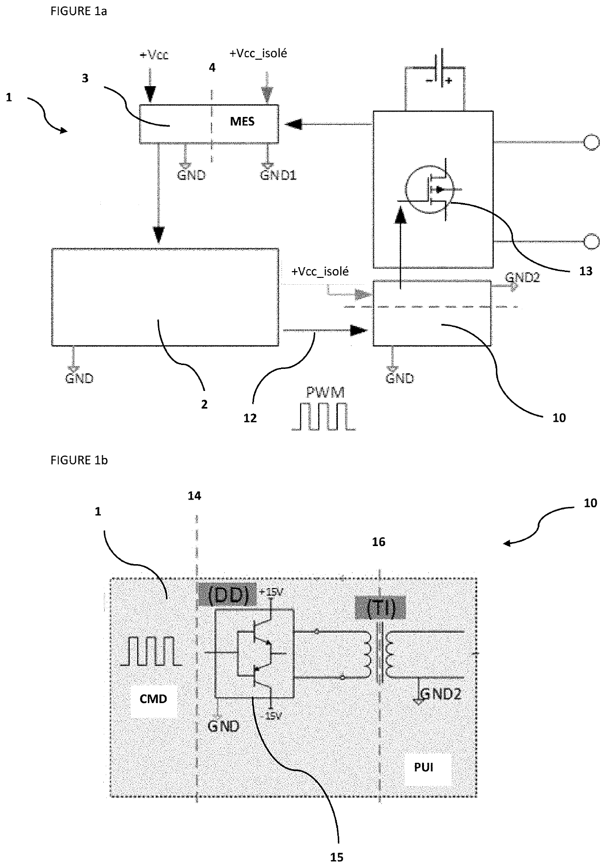
[0023]Electronic power systems (1) provides several functions depending on the applications for which they are used, such as notably motor control for torque variation, source conversion between a DC electrochemical accumulator and an AC distribution network, voltage level adaptation between two DC sources and power variation.

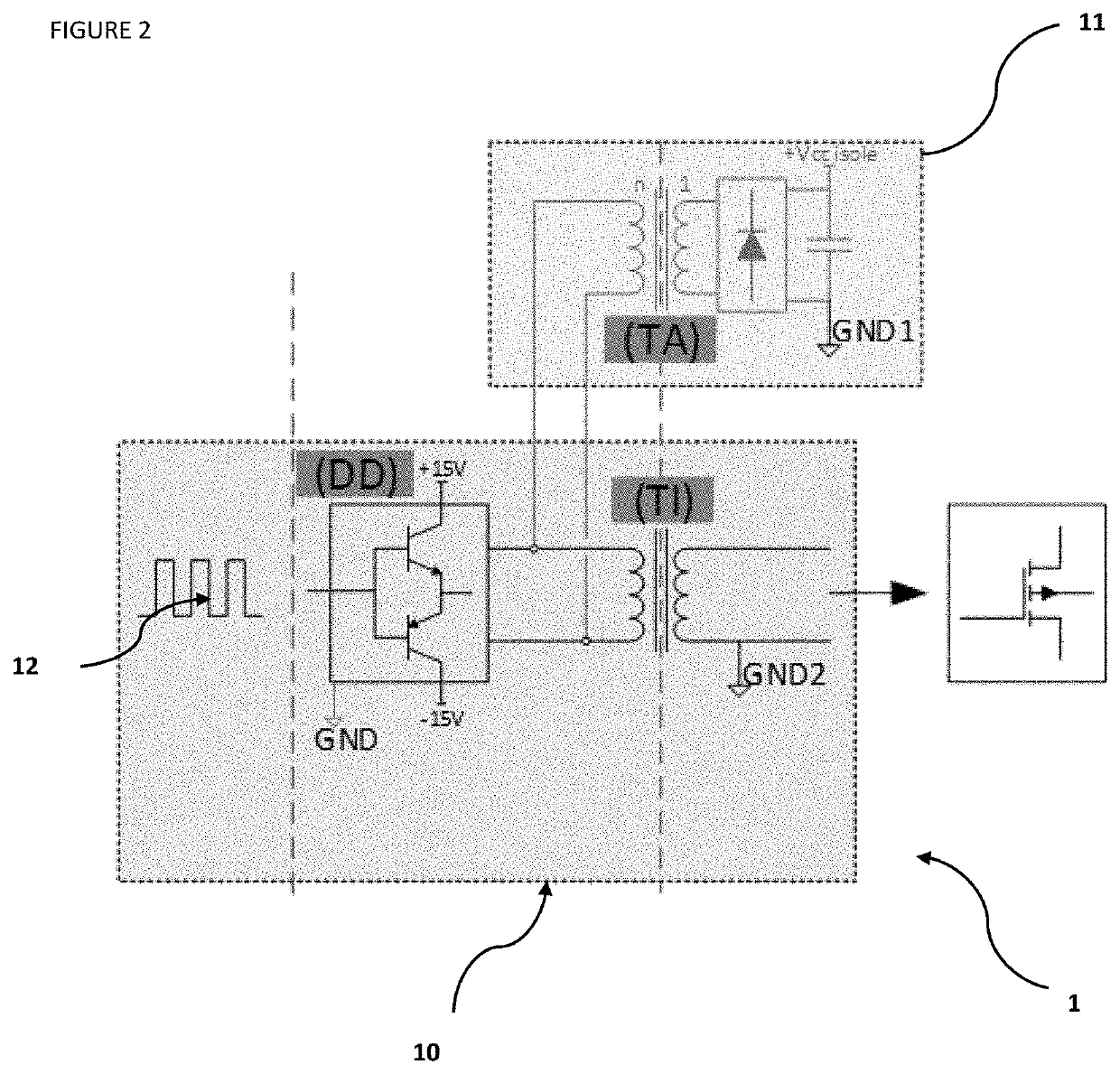
[0024]As mentioned above, a large majority of these systems, from a few tens of watts to several hundreds of kilowatts, are referred to as switch-mode systems. They have semiconductor switches (13) capable of switching, at high frequencies, high currents and voltages.

[0025]FIG. 1a illustrates, a block diagram, functions of an electronic power system (also referred to as energy conversion system) as described and which is generally found in the state of the art. This diagram is also the one found within the invention described hereafter. In the figures, references to GND corresponds to the electrical ground.

[0026]Such an electronic system (1) comprises a measure...


PUM


Abstract

The invention is an electronic power system (1) for energy conversion, comprising at least one electronic amplifier driver circuit (10), at least one floating-ground isolated power supply (11) and at least one digital computation unit (2) for generating control signals (12). The invention more specifically relates to a floating-ground isolated power supply (11) from control signals (12).

Description

CROSS-REFERENCE TO RELATED APPLICATIONS[0001]Reference is made to International Application No. PCT / EP2019 / 054851, filed Feb. 27, 2019, which claims priority to French Patent Application No. 18 / 52.011, filed Mar. 8, 2018, the contents of which are incorporated herein by reference in their entirety.BACKGROUND OF THE INVENTION[0002]Field of the Invention The present invention relates to the field of electronic power systems, and more specifically to systems for converting energy between alternating current (AC) and direct current (DC). The present invention more specifically concerns the production of an isolated power supply generated from the energy conversion system.BACKGROUND OF THE INVENTION[0003]Electronic power systems fulfil different functions according to the applications in which they are used. By way of non-limitative example, motor control for torque variation, source conversion between a DC electrochemical accumulator and an AC distribution network, voltage level adaptat...

Claims


Application Information

Patent Timeline
IPC IPC(8): H02M1/08H03K17/691H02M3/335
CPCH02M1/08H03K17/691H02M2001/0009H03K2217/0081H02M3/33523H02M1/00H02M1/0006H02M1/0009
Inventor OLSZEWSKI, DIMITRIBATTISTON, ALEXANDRE
Owner INST FR DU PETROLE
Why Eureka
Try Eureka