Mud flap holder system

Active Publication Date: 2005-05-26
BETTS SPRING
View PDF12 Cites 14 Cited by
  • Summary
  • Abstract
  • Description
  • Claims
  • Application Information

AI Technical Summary

Benefits of technology

[0006] The present invention relates to a system which allows for the separation without damage of a mud flap from a holder assembly when pulling forces are exerted on the mud flap without causing damage to the

Problems solved by technology

It is a common failure mode for these flaps to become trapped between the ground and the tires, when the vehicle is traveling in reverse.
This creates a strong pulling force on the f

Method used


Image

  • Mud flap holder system
  • Mud flap holder system
  • Mud flap holder system

Examples


Embodiment Construction

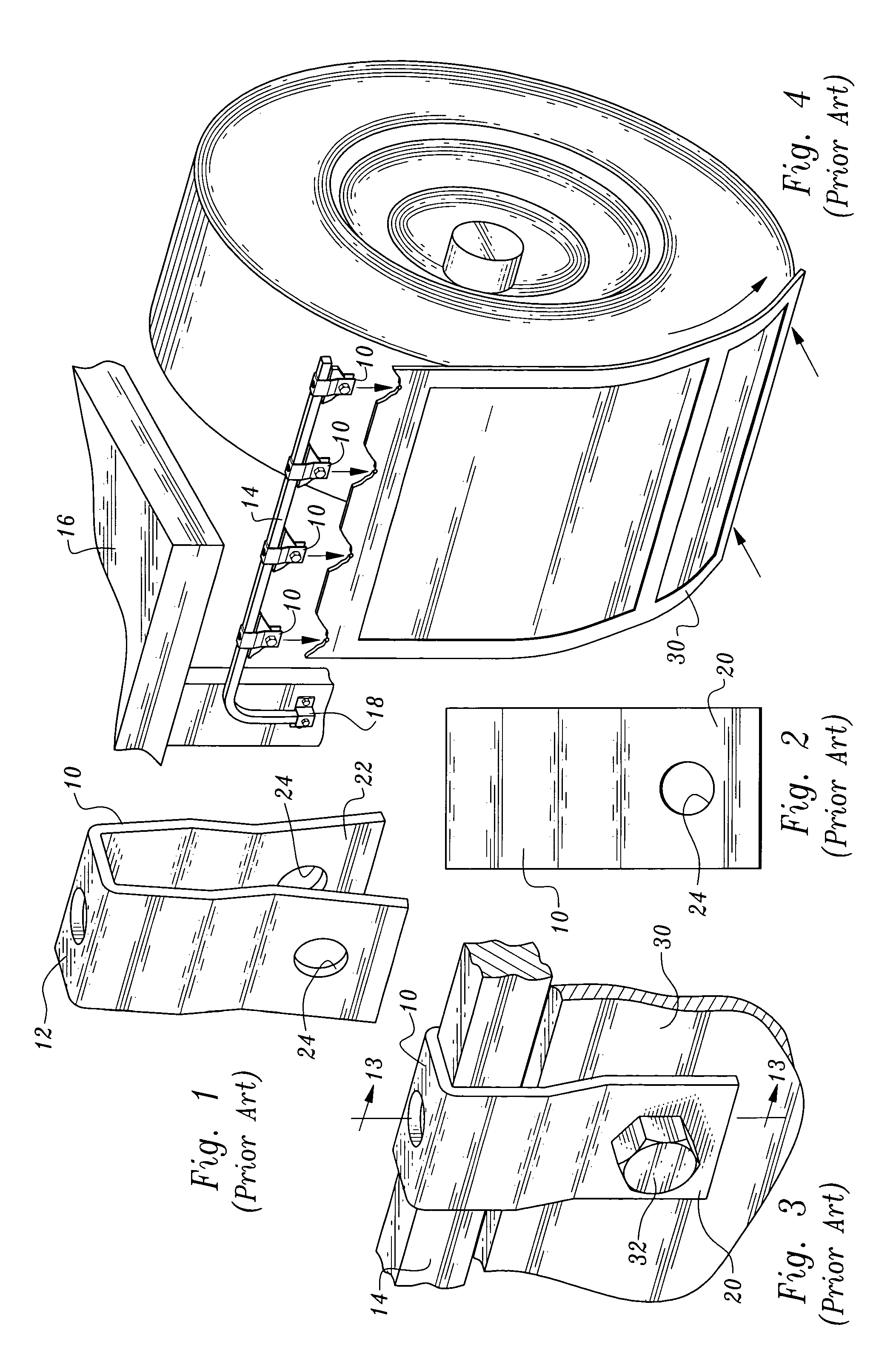
[0025] Referring now to FIGS. 1-4 and 13, a conventional mud flap support clip and mud flap holder assembly are illustrated.

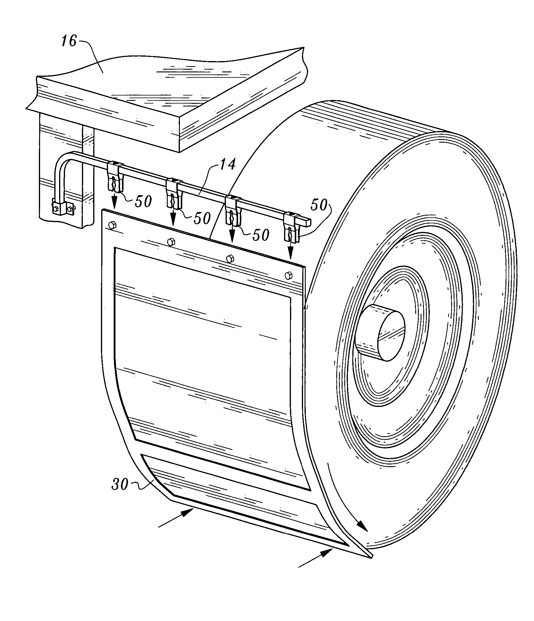
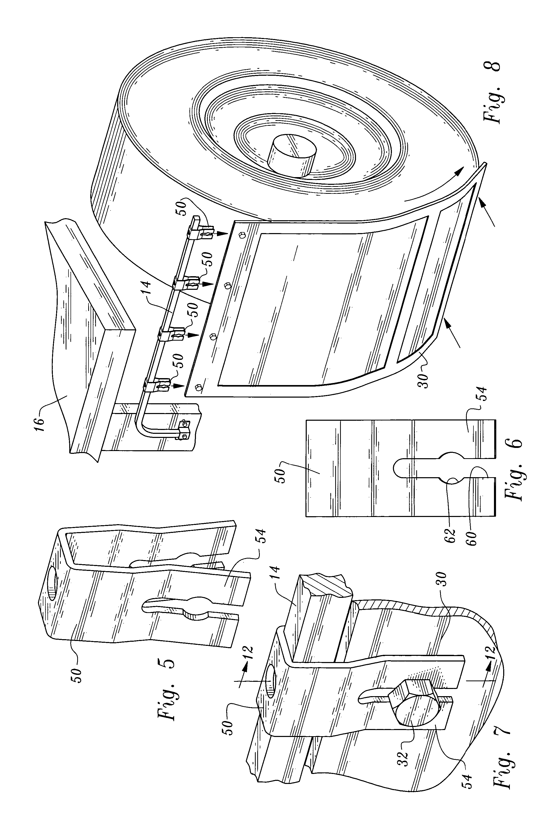
[0026] The conventional mud flap support clip 10 is of integral construction, typically being formed from sheet metal. The support clip 10 has a flat central portion 12 which is positioned on and engages a support member 14 in the form of an elongated bent bar affixed to a vehicle 16 by a bracket 18. FIG. 4 shows four support clips 10 on the support member.

[0027] Integral with and extending downwardly from central portion 12 are two clip segments 20, 22. Holes 24 are formed in the clip segments.

[0028] Conventional mud flap 30 depends from the support clips 10. The mud flap has four apertures (not shown) formed therein which are placed in alignment with holes 24 of the support clips. Mud flap securement bolts 32 extend through holes 24 and the holes in the top portion of the flap and the mud flap is secured in place by applying nuts 34 (see FIG. 13) to the bo...


PUM


Abstract

A mud flap holder assembly includes a mud flap support clip bifurcated at one of the ends thereof to define an open ended variable width slot. The mud flap is held in position by a bolt positioned in the slot with portions of the support clip defining the slot forming a detent frictionally releasably engaging the flap.

Description

TECHNICAL FIELD [0001] The present invention relates to apparatus including mud flap holder structure which enables a mud flap on a truck or other motor vehicle to be released from the vehicle when trapped between the ground and a tire or when other pulling. forces of a predetermined magnitude are applied to the mud flap to avoid damage to the mud flap and holder structure. BACKGROUND OF THE INVENTION [0002] Mud flap holders on large trucks are in close proximity to the driving wheels. It is a common failure mode for these flaps to become trapped between the ground and the tires, when the vehicle is traveling in reverse. This creates a strong pulling force on the flap and flap holder structure which can damage or break one or both components. [0003] There have been various approaches meant to address this problem—typically involving a spring released channel mechanism, which is added to a standard flap and flap holder. Other designs use a series of metal stampings, working in conjun...

Claims


Application Information

Patent Timeline
IPC IPC(8): B62D25/18
CPCB62D25/188
Inventor BARR, GRAYLIN PATRICKBETTS, WILLIAM MICHAEL IVBETTS, WILLIAM MICHAEL VDAY, STANLEY H.
Owner BETTS SPRING
Why Eureka
Try Eureka