Child-resistant containers and packaging

a technology for containers and packaging, applied in the field of child-resistant containers and/or packaging, can solve the problems of users having to use both hands, difficult (if not impossible) for children under a certain age to open containers or packages, and frustration for younger children to comparatively do the same, so as to reduce the cost of longer-term ownership

Active Publication Date: 2022-01-11
RAYMOND CHRISTOPHER ENTERPRISES LLC
View PDF11 Cites 3 Cited by
  • Summary
  • Abstract
  • Description
  • Claims
  • Application Information

AI Technical Summary

Benefits of technology

[0007]In one embodiment, a child-resistant container as disclosed herein may include a receptacle having an inner cavity, a lid that selectively couples with the receptacle in pivoting relation about a hinge to enclose the inner cavity when in a locked position, and a lock movable between the locked position securing the lid to the receptacle to substantially prevent access to the inner cavity and an unlocked position permitting the lid to move relative to the receptacle to expose access to the inner cavity. The child-resistant container may be made from a metal material selected from the group consisting of steel, aluminum, or a metal alloy. Alternatively, the child-resistant container may be made from a paper-based material, such as cardboard or the like. In some embodiments, a food-grade protective sheath may be disposed within an inner surface of the inner cavity and / or within an inner surface of the lid and may be selectively removable and / or replaceable so as to reduce longer-term ownership costs associated with the child-resistant container. In embodiments wherein the lock is disposed within the inner cavity, the protective sheath may also include an indent having a size and shape to accommodate the lock thereunder.
[0008]One or more of the sidewalls of the receptacle may include an annular shoulder vertically extending upwardly from a base and transitioning at an inwardly projecting step to an interiorly located upper rim having a wall thickness relatively smaller than the annular shoulder. The lid may include a downwardly extending annular skirt that selectively lands in seated relation on the inwardly projecting step and adjacent the upper rim when the child-resistant container is in the locked position. When seated, the downwardly extending annular skirt may encompass the upper rim to substantially prevent side-to-side movement relative thereto, to help prevent access to the inner cavity. To this end, the lock may include at least one locking catch outwardly extending from the receptacle that may include a downwardly facing planar shoulder that engages an inwardly curved lip of the annular skirt when the lid is in the locked position. Here, the lock may also include at least one channel having a spring therein that normally biases the locking catch and an integrally formed release button in a forward position externally accessible from the receptacle, wherein depression of the release button causes simultaneous movement of the normally hidden release button out from engagement with the inwardly curved lip, to release the lid from engagement with the receptacle. The at least one locking catch may also include a rounded upper surface opposite the downwardly facing planar shoulder to facilitate reconnection of the inwardly curved lip over the locking catches when pivoting the lid from the unlocked position to the locked position.
[0009]In another aspect of these embodiments, the lid may include an outer housing having a size and shape for select slide-in reception of the receptacle. Here, the receptacle may include a pair of safety tabs outwardly extending therefrom and normally residing forwardly in a pair of respective locking channels formed in the lid when the child-resistant container is in the locked position. The locking channels may also be in slideable relation with a pair of respective rearly positioned and relatively larger release channels. In these embodiments, the lid may include a spring that biases the receptacle into a forward position within the lid to locate the safety tabs into the respective locking channels. When in this locked position, a front end of the receptacle may protrude out from within the lid. To this end, the lid may also include a notch exposing a relatively larger surface area of the receptacle for enhanced hand manipulation re pull-out removal. When aligned with the release channels in the lid from at least partial compression of the spring with the receptacle, the safety tabs may pivot between a normal vertical position extending out from within the lid and a folded position adjacent a sidewall of the receptacle and within an interior of the lid, thereby permitting slide-out removal of the receptacle from the lid.
[0011]In another aspect of this embodiment, the lock may be disposed within the inner cavity and a food-grade protective sheath may be disposed over an inner surface of the inner cavity and include an indent having a size and shape to accommodate the lock thereunder. Moreover, at least one sidewall of the receptacle may include an annular shoulder vertically extending upwardly from a base and transitioning at an inwardly projecting step to an interiorly located upper rim having a wall thickness relatively smaller than the annular shoulder. Here, the inwardly projecting step may have a size and shape to receive a downwardly extending annular skirt of the lid in seated reception thereof when the child-resistant container is in the locked position. As such, the downwardly extending annular skirt may encompass the upper rim when in seated reception on the inwardly projecting step. In another aspect of this embodiment, the catch may include a rounded upper surface opposite a downwardly facing planar shoulder to facilitate locking and unlocking.
[0012]In another embodiment, the child-resistant container may include a receptacle having an inner cavity, a lid forming an outer housing having a size and shape for select slide-in reception of the receptacle to enclose the inner cavity when in a locked position, and a lock including a safety tab outwardly extending from the receptacle and normally residing forwardly in a locking channel formed in the lid when the child-resistant container is in the locked position, to substantially prevent access to the inner cavity. Here, a spring in the form of a foam pad located within the lid may bias the receptacle into a forward position within the lid to locate the safety tab into a locking channel. When in the locked position, a front end of the receptacle may protrude out from the lid and include a notch therein to expose a relatively larger surface area of the receptacle for enhanced hand manipulation.

Problems solved by technology

Accordingly, this would allow adults—having a certain minimum level of dexterity greater than that of younger children—to open the containers to access product therein, while effectively frustrating a younger child's ability to comparatively do the same.
In time, products created in response to the PPPA have become known as childproof or child-resistant containers and / or packaging due to design features that make it difficult (if not impossible) for children under a certain age to open the container or package to access the contents therein.
Still, users necessarily need to use both hands to overcome the child resistant feature to unscrew the closure cap.
While deployment of the abovementioned child-resistant container and cap combination has been effective for use with traditional prescription medications (typically sold in pill or capsule form), in recent years, new issues have arisen as a result of medical products being disseminated in other configurations, such as consumables (e.g., gummies, chocolates, candies, and other like food products).
Although, the problem with these so-called “exit” bags is that, once home, studies have shown that buyers remove the products (e.g., vaporizers, edibles, flowers, etc.) from the packaging for storage in open or otherwise easily accessible containers that children can access.
Thus, children may be exposed to medical marijuana products around the house in what largely amounts to unsafe storage containers and packaging.
Current child proof or resistant packaging on the market does not meet the needs for securely storing product or otherwise making it inaccessible for storing medical products or the like post-purchase.

Method used


Image

  • Child-resistant containers and packaging
  • Child-resistant containers and packaging
  • Child-resistant containers and packaging

Examples


Embodiment Construction

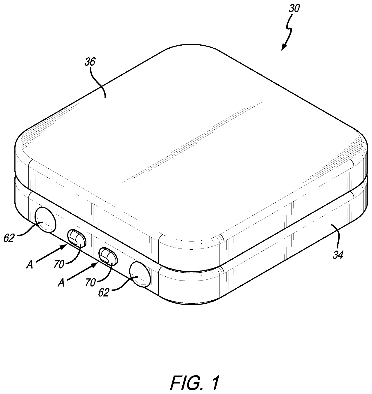
[0044]As shown in the exemplary drawings for purposes of illustration, the present invention for a child-resistant container and / or package is generally illustrated with respect to one embodiment of a child-resistant tin 30 in FIGS. 1-12 and with respect to a second embodiment of a child-resistant box 32 in FIGS. 13-28. As disclosed in more detail herein, the child-resistant tin 30 and the child-resistant box 32 are particularly ideal for both dispensary compliance purposes at the point of sale and for safe home use as each provides a container for continued safe storage after purchase.

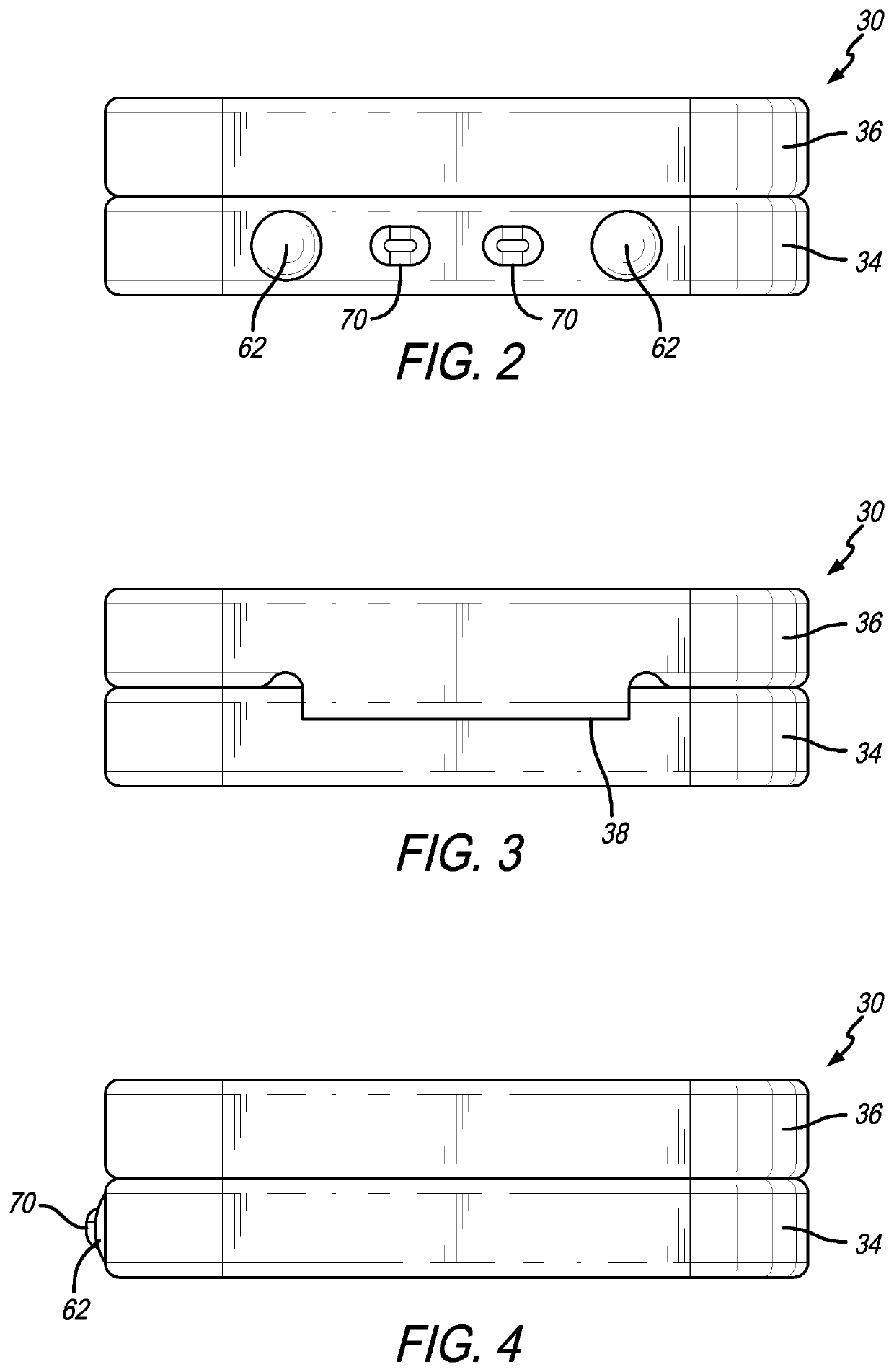
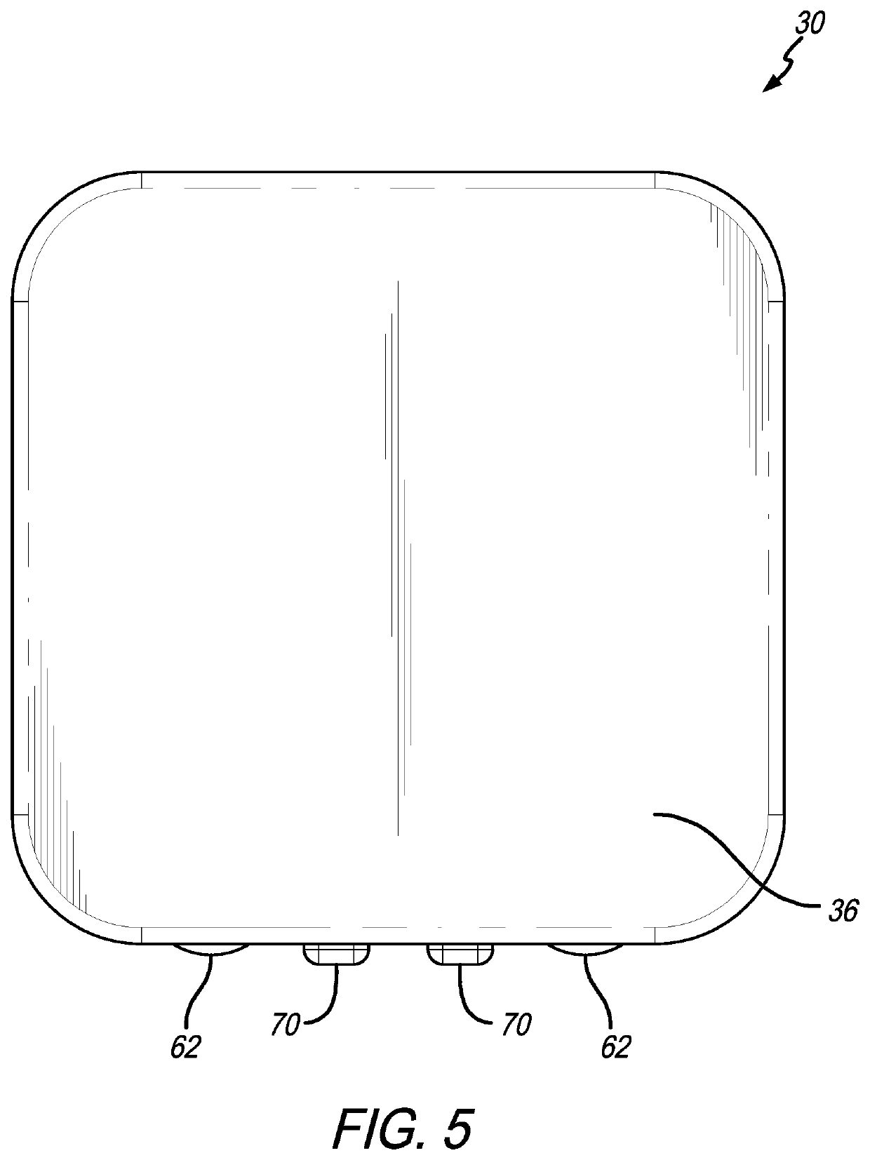
[0045]More specifically, the child-resistant tin 30 illustrated, e.g., in FIG. 1, includes a storage container 34 coupled to a lid 36 about a hinge 38. In general, as illustrated in FIGS. 1-9, the storage container 34 and the lid 36 are each generally of a rectangular shape, although a person of ordinary skill in the art would recognize that the shape may vary (e.g., square, circular, etc.). Each of t...


PUM


Abstract

The child-resistant container includes a receptacle having an inner cavity, a lid that selectively couples with the receptacle to enclose the inner cavity when in a locked position, and a lock movable between the locked position securing the lid to the receptacle to substantially prevent access to the inner cavity and an unlocked position permitting the lid to move relative to the receptacle to expose access to the inner cavity. The receptacle and lid combination may include a lid that pivots relative to a container about a hinge and locks thereto by locking catches in the container sidewalls; or may include an outer housing enclosing an inner storage container in slide-in relation, wherein a pair of safety tabs extend from the inner storage container and through the outer housing into a respective pair of locking channels formed therein.

Description

BACKGROUND OF THE INVENTION[0001]The present invention generally relates to child-resistant containers and / or packaging. More specifically, the present invention relates to child-resistant containers and / or packaging that include a safety lock or latch or a pair of safety tabs requiring a desired minimum level of dexterity to disengage before the container or package may be opened to access contents therein.[0002]In 1970, Congress enacted the Poison Prevention Packaging Act (“PPPA”) in response to a relatively high number of children ingesting hazardous household products (e.g., ranging from household cleaning products to prescription medications). According to the U.S. Consumer Products Safety Commission (“CPSC”) at the time, poisonings from household products were one of the leading causes of injuries for children under five. Thus, the PPPA was designed to establish a new set of regulations that govern the safety of packaging products that could be harmful to young children if ing...

Claims


Application Information

Patent Timeline
Patent Type & Authority Patents(United States)
IPC IPC(8): B65D43/16B65D50/00B65D55/02B65D5/38B65D25/14
CPCB65D50/00B65D5/38B65D25/14B65D43/163B65D55/02B65D50/046B65D2215/02B65D2251/1058
Inventor KACHIAN, RUBENTOROYAN, MIKE
Owner RAYMOND CHRISTOPHER ENTERPRISES LLC
Why Eureka
Try Eureka