Weak current equipment connection state collecting device and method

A connection status and collection device technology, applied in electrical connection testing, measuring devices, aerospace equipment, etc., can solve problems such as failure to find errors in time, burning modules, failure to find connection errors in time, etc.

Active Publication Date: 2019-04-23
XIAN HAIZHOU INFORMATION TECH
View PDF12 Cites 1 Cited by
  • Summary
  • Abstract
  • Description
  • Claims
  • Application Information

AI Technical Summary

Problems solved by technology

[0004] First, the application system composed of modules mounted on the installation board cannot detect connection errors in time with traditional methods, and the workload for detecting errors in complex systems is very large, which brings certain difficulties to the teacher's guidance
[0005] Second, because the traditional method is for students to connect according to the teaching m

Method used


Image

  • Weak current equipment connection state collecting device and method
  • Weak current equipment connection state collecting device and method
  • Weak current equipment connection state collecting device and method

Examples


Embodiment 1

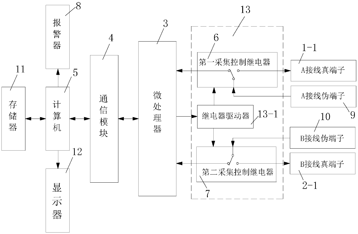
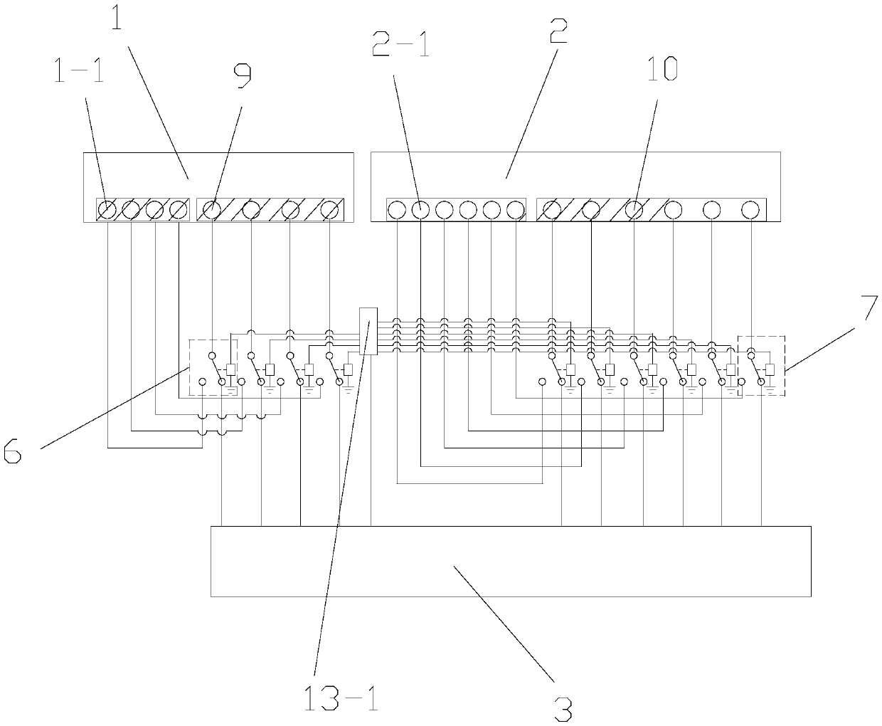
[0054] like figure 1 The device for collecting the connection state of weak current equipment includes A equipment 1 and B equipment 2 arranged on the front side of the training operation panel, a pseudo-connection terminal arranged on the front side of the training operation panel and provided for trainers to train, and The real connection terminal arranged on the rear side of the training operation panel, and the terminal collection connection module for collecting the connection state of the pseudo connection terminal and for actually connecting the real connection terminal, and the terminal connection module connected with the terminal collection connection module Computer monitoring module, the real connection terminal includes a plurality of A connection real terminals 1-1 that A equipment 1 has and a plurality of B connection real terminals 2-1 that B equipment 2 has, and the pseudo connection terminal includes a The A connection dummy terminal 9 corresponding to the co...

Embodiment 2

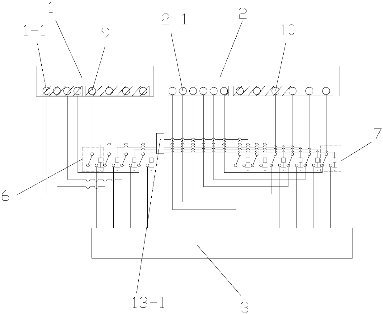
[0096] like image 3 As shown, in this embodiment, the difference from Embodiment 1 is that the normally closed contact of the first collection control relay 6 is connected to the true terminal 1-1 of the A connection, and the normally closed contact of the first collection control relay 6 The open contact is connected with the microprocessor 3, the normally closed contact of the second acquisition control relay 7 is connected with the true terminal 2-1 of the B connection, the normally open contact of the second acquisition control relay 7 is connected with the microcomputer Processor 3 is connected.

[0097] In this embodiment, it should be noted that when the normally closed contact of the first collection control relay 6 is connected to the true terminal 1-1 of the A connection, the normally closed contact of the second collection control relay 7 is connected to the true terminal 1-1 of the B connection. The terminals 2-1 are connected, that is, the A device 1 and the B d...


PUM


Abstract

The invention discloses a weak current equipment connection state collecting device and method. The weak current equipment connection state collecting device comprises equipment A, equipment B, a microprocessor and a pseudo wiring terminal. A computer monitoring module comprises a computer, a memory, an alarm and a display, wherein the memory, the alarm and the display are connected with the computer. The weak current equipment connection state collecting method comprising the steps that 1, connection terminals are subjected to numbering; 2, a correct connection database and an incorrectly connection database are established; 3, the connection state of the pseudo wiring terminal is collected; and 4, the connection state of the pseudo wiring terminal and the connection of the display deviceare determined. The weak current equipment connection state collecting device and method have reasonable design, simple operation, high molding efficiency and a good use effect, can accurately collect the connection state of weak current equipment in a training module, facilitates the repeat connection of a trainer, and facilitates teaching and training.

Description

technical field [0001] The invention belongs to the technical field of connection status of weak current equipment, and in particular relates to a collection device and method for connection status of weak current equipment. Background technique [0002] At present, domestic higher education, especially vocational education, has higher and higher requirements for engineering training, and the common electronic engineering training products on the market are application systems composed of modules mounted on the mounting board. The training method for the training circuit board is to verify the correctness of the circuit or the function of a certain device through the provided training guide, and it cannot be verified for the wrong design. For the practical training method of installing functional modules on the mounting board, the installation is carried out under the guidance of the training guide. Whether the installation is correct or not can not be found in time, and th...

Claims


Application Information

Patent Timeline
IPC IPC(8): G01R31/04G09B9/00
CPCG01R31/67G09B9/00
Inventor 权斌权溦徐红
Owner XIAN HAIZHOU INFORMATION TECH
Why Eureka
Try Eureka