Method and system for LED temporal dithering to achieve multi-bit color resolution

a technology of led time delay and color resolution, applied in the field of visual indicators and warning devices, can solve the problems of limited number of colors that can be usable, limited number of colors can be achieved, and limited existing displays

Inactive Publication Date: 2005-05-26
NOVARTIS AG
View PDF6 Cites 33 Cited by
  • Summary
  • Abstract
  • Description
  • Claims
  • Application Information

AI Technical Summary

Problems solved by technology

Further, within these limited choices the colors themselves are limited to either red / green bi-color LEDs or red, green, and blue tri-color LEDs.
The range of possible indications from the same LED and the ability to transmit information to a viewer through a multi-color display is thus limited by current LED technology.
While it is desirable to have multi-color capable indicators for rapid and accurate transmission of information from an electronic system to an operator, the limitations of currently existing LED technology are such that only a limited number of colors can be usably achieved.
Further, these existing displays are limited in that the color of each LED in a display cannot be changed beyond the current state of the art of three colors per LED (e.g., when using tri-color LEDs).
Therefore, while it is desirable to have more than three colors available for display within the same or IS multiple LED indicators, it is not feasible using the currently available LED technology.

Method used


Image

  • Method and system for LED temporal dithering to achieve multi-bit color resolution
  • Method and system for LED temporal dithering to achieve multi-bit color resolution
  • Method and system for LED temporal dithering to achieve multi-bit color resolution

Examples


Embodiment Construction

[0019] Preferred embodiments of the present invention are illustrated in the FIGUREs, like numerals being used to refer to like and corresponding parts of the various drawings.

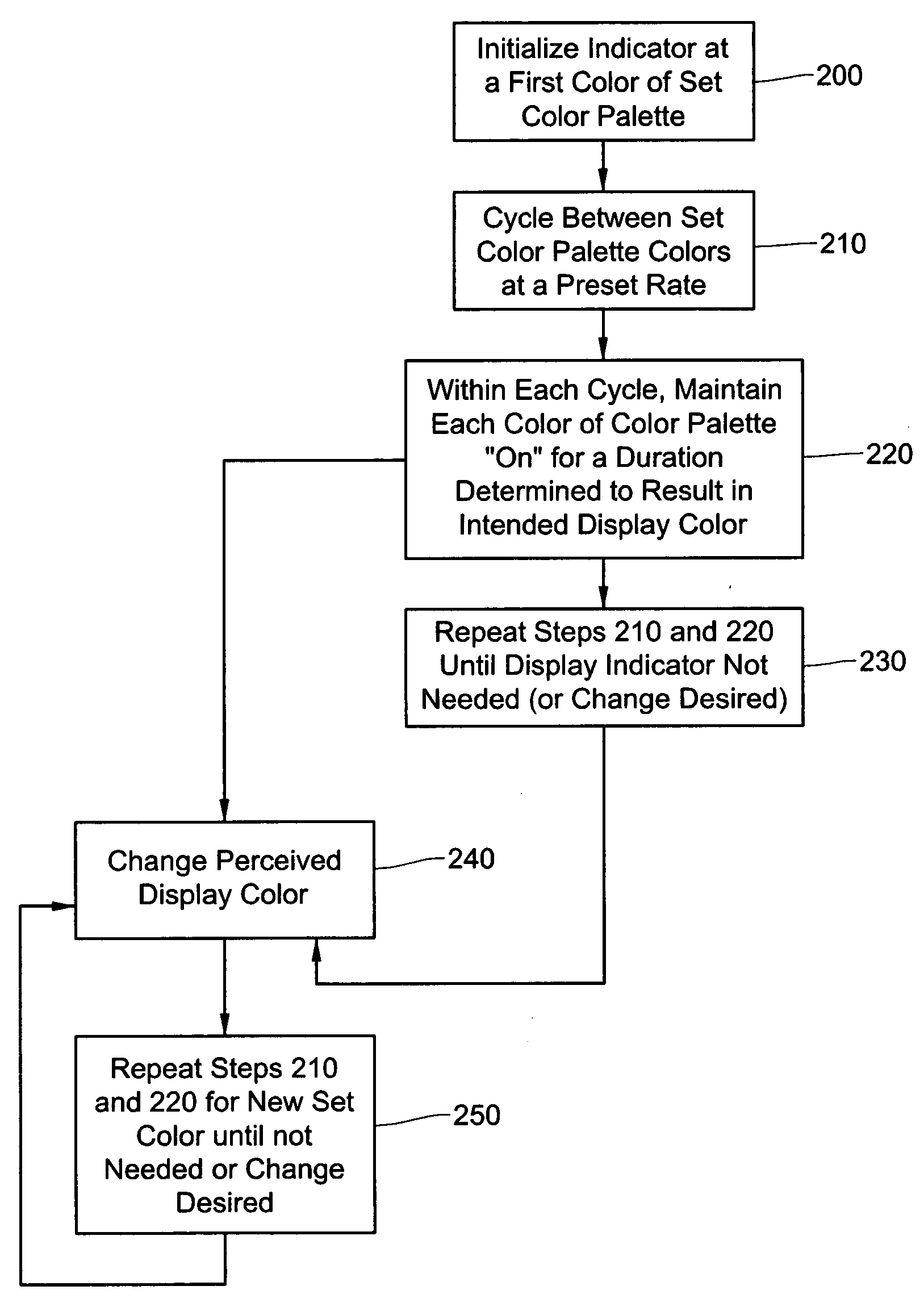
[0020] The various embodiments of the present invention provide for temporal dithering of an LED indicator to achieve a multi-bit color resolution display. Sequential altering of the colors, in, for example, a bi-color or a tri-color LED, at a sufficiently high rate (e.g., greater than 60 kHz) creates a visual perception of a desired color in human vision (different colors being achieved at different frequencies). The method of this invention is in contrast to intensity half-toning, in which all colors are lit simultaneously, but with different intensity amplitudes. Cycling between, for example, the red, green, and blue colors of a tri-color LED (Light Emitting Diode) indicator, at different frequencies can create any visible color tone within the color gamut achievable at the intensities of the LED. Multi-bi...


PUM


Abstract

A method and system for temporal dithering of an LED indicator are disclosed, one embodiment of the method comprising: initializing the LED indicator to display a first color of a color palette; during each cycle of a preset cycling rate, cycling the LED indicator display color between the first color and one or more selected colors of the color palette, wherein the LED indicator is caused to display in turn the first color and each selected color of the color palette for a preset portion of each cycle determined to result in a perceived display color at the LED indicator; and repeating the cycling step to maintain the perceived display color at the LED indicator. The method can further comprise the step of changing the perceived display color to a new perceived display color. Changing the perceived display color can comprise: adjusting the size of the preset portion of each cycle allotted to each of the first color and the one or more selected colors for display, wherein the size of each preset portion is determined to result in the new perceived display color; and repeating the cycling step using the adjusted preset portion sizes to maintain the new perceived display color at the LED indicator. Further, changing the perceived display color can be manually initiated or automatically initiated in response to a changing condition. The changing condition can be, for example, an exceeded limit of a parameter associated with the LED indicator.

Description

TECHNICAL FIELD OF THE INVENTION [0001] This application claims priority from U.S. Ser. No. 60 / 524,966 filed Nov. 25, 2003. [0002] The present invention relates generally to the field of visual indicators and warning devices. In particular, the present invention relates to visual indicators for use in surgical devices. Even more particularly, the present invention relates to the temporal dithering of Light Emitting Diode (“LED”) indicators for achieving multi-bit color resolution LED displays.BACKGROUND OF THE INVENTION [0003] Light Emitting Diodes (“LEDs”) are commonly used as indicators in a variety of applications, ranging from consumer electronics (e.g., stereo status displays, power on / off indicators, etc.) to commercial applications such as in manufacturing control consoles, avionics, and surgical systems. However, commonly available LEDs, as known to those familiar with the art, are typically either single color, bi-color (two-bit color), or, more recently, tri-color (three-b...

Claims


Application Information

Patent Timeline
Patent Type & Authority Applications(United States)
IPC IPC(8): G09G3/14G09G5/10
CPCG09G3/14
Inventor GOLDSCHMIDT, ALAN B.ARTSYUKHOVICH, ALEXANDER N.
Owner NOVARTIS AG
Why Eureka
Try Eureka