
Electrical connector assembly

a technology of electrical connectors and connector assemblies, applied in the direction of live contact access prevention, coupling device connection, electrical apparatus, etc., can solve the problems of exacerbate corrosion problems, environmental conditions are particularly harsh, and the process is susceptible to corrosion and other degrading processes

Inactive Publication Date: 2009-08-18
STREETCAREC SLOAN
View PDF45 Cites 46 Cited by
  • Summary
  • Abstract
  • Description
  • Claims
  • Application Information

AI Technical Summary

Benefits of technology

"The invention relates to a plug for an electrical connector assembly that can be easily gripped and retained in a socket. The plug has a body with a receptacle and at least one electrical terminal. A catch on the socket and a catch receiver on the plug can mate to secure the plug in the socket. A resilient seal is located at the distal end of the body and surrounds the mating electrical terminals, compressing against the receptacle wall. The catch can be a key or a finger on the closure of the receptacle. The plug can also have a knob with a bulbous portion and a neck connecting the body to the knob. The knob can be designed to accommodate the user's fingers and prevent fluid from flowing. The technical effects of the invention include improved grip and retention of the plug in the socket, as well as improved sealing to prevent fluid leakage."

Problems solved by technology

The metallic connections in plugs and sockets, even when the plug and the socket are connected to one another, are exposed to the environment and therefore susceptible to corrosion and other degrading processes.
Thus, environmental conditions are especially harsh during the winter in areas where salt and other chloride containing chemicals, such as calcium chloride, are applied to the roads.
Further, a practice called “pre-wetting” where the chemicals are wet prior to application to the road to increase effectiveness and decrease the tendency for the chemicals to be blown off the road has become common and can exacerbate corrosion problems.
Even if the chemicals are left to dry, the solid crystals are very hydroscopic and, therefore, attract moisture to form a wet mixture, which is more corrosive than dry chloride containing chemicals.

Method used


Image

  • Electrical connector assembly
  • Electrical connector assembly
  • Electrical connector assembly

Examples


Embodiment Construction

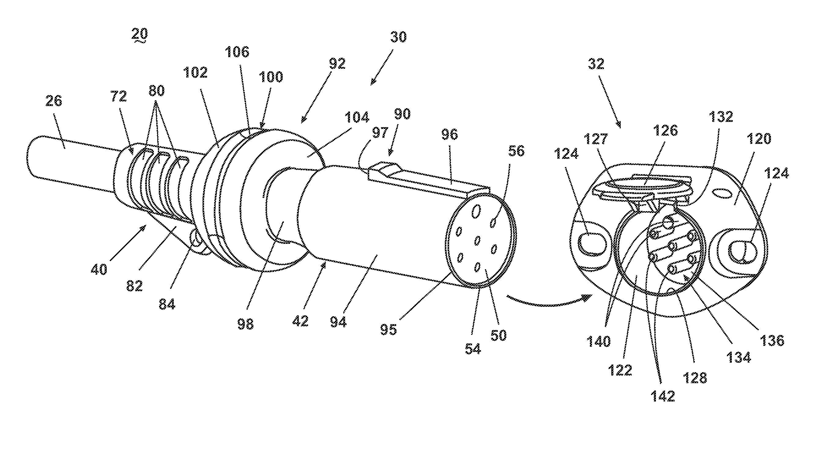
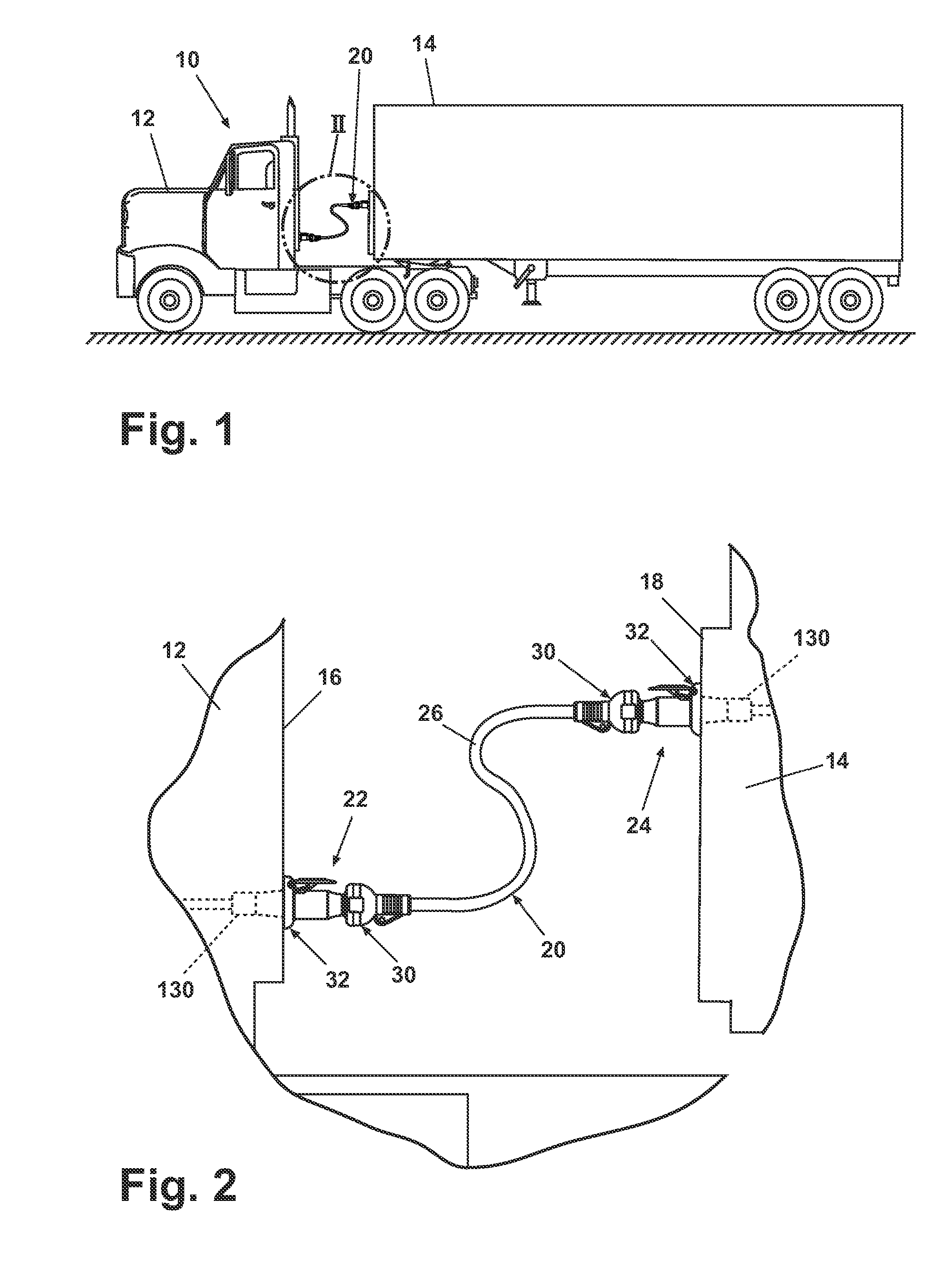
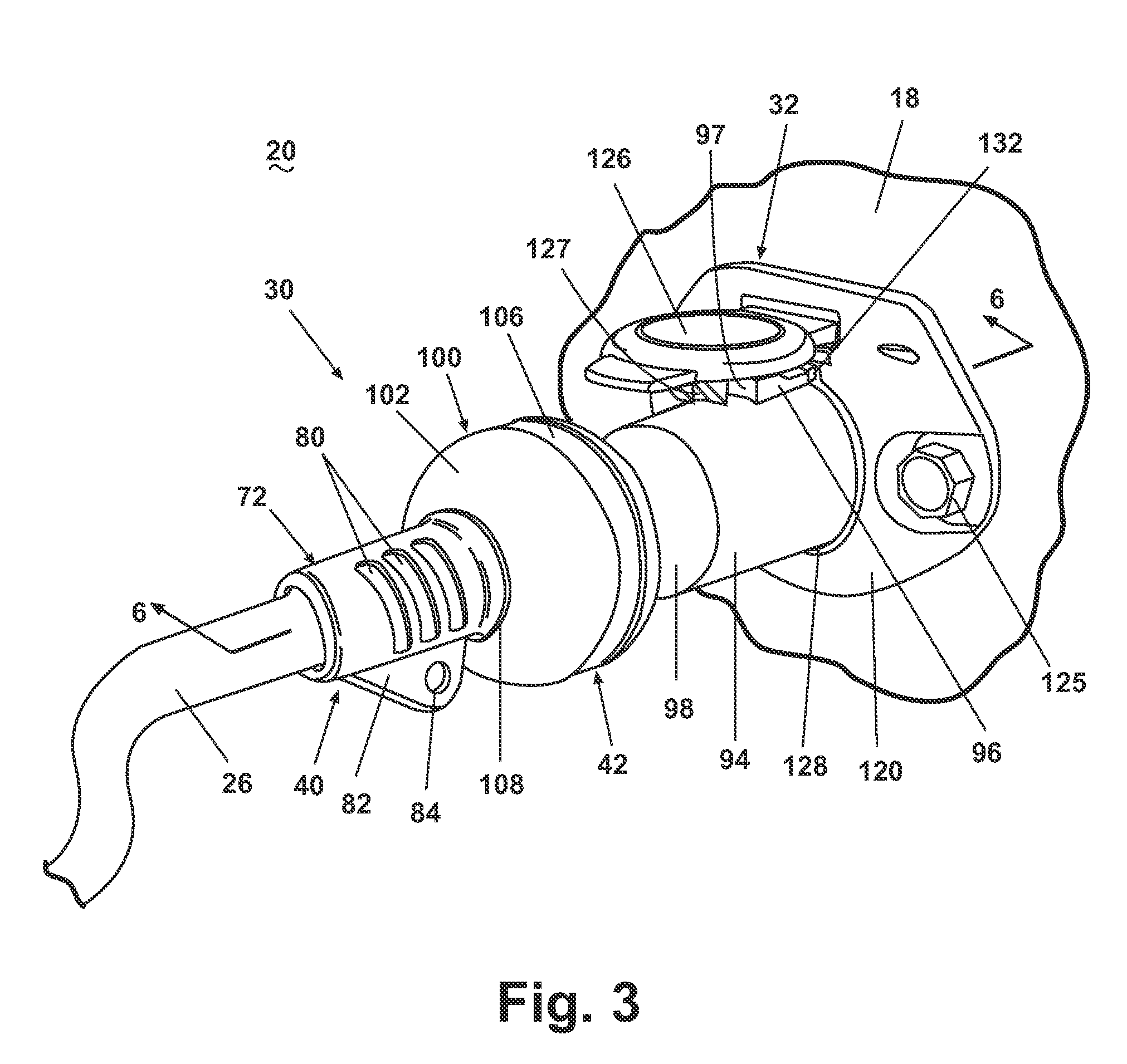
[0031]Referring now to the figures, FIG. 1 illustrates an exemplary, conventional tractor-trailer 10 comprising a tractor 12 electrically coupled to a trailer 14 by an electrical connector assembly 20 according to one embodiment of the invention. As shown in FIG. 2, which is an enlarged view of the area labeled II in FIG. 1, the tractor 12 includes a rear wall 16 that supports a tractor portion 22 of the electrical connector assembly 20, and, similarly, the trailer 14 has a front wall 18 that supports a trailer portion 24 of the electrical connector assembly 20. The tractor portion 22 and the trailer portion 24 are connected by a cable 26 of sheathed electrical wires to electrically couple the tractor 12 to the trailer 14. The cable 26 terminates at a pair of plugs 30, which are removably received by a corresponding socket 32 mounted to the corresponding rear wall 16 of the tractor 12 or the front wall 18 of the trailer 14. While the electrical connector assembly 20 is shown and des...


PUM


Abstract

An electrical connector assembly, such as for use with a tractor-trailer, comprises a socket and a plug. The plug can comprise a resilient seal configured to surround mating electrical terminals on the socket and the plug. A coupler can be configured to retain the plug in the socket and compress the resilient seal against the socket. The plug can further comprise a knob having a bulbous portion sized to fit in a palm of a user's hand for ease of grasping by the user. The knob can include a drip edge.

Description

CROSS-REFERENCE TO RELATED APPLICATION[0001]This application claims the benefit of U.S. Patent Application No. 60 / 594,271, filed Mar. 24, 2005, the complete disclosure of which is incorporated by reference.BACKGROUND OF THE INVENTION[0002]1. Field of the Invention[0003]The invention relates generally to an electrical connector assembly for a tractor-trailer and particularly to a tractor-trailer electrical connector assembly that withstands potentially degrading environmental conditions.[0004]2. Description of the Related Art[0005]Electrical connector assemblies known in the art as a seven-way assembly are well known devices that electrically communicate a tractor with a trailer or electrically communicate adjacent trailers for operation of a variety of electrical systems, including brake lights, running lights, turn signal lights, and anti-lock braking systems. Because the tractor-trailer is a modular assembly, wherein the trailer can be viewed as an interchangeable component, all t...

Claims


Application Information

Patent Timeline
Patent Type & Authority Patents(United States)
IPC IPC(8): H01R13/44
CPCH01R13/639H01R13/5219H01R31/06
Inventor WILLIAMS, LIBBYKARAFA, ANTHONYTERRYN, CHRISTOPHERKUIPERS, TODD M.HELMER, CHRISTOPHER R.
Owner STREETCAREC SLOAN
Learn More