Flashlight having manual charging device

a charging device and flashlight technology, applied in the field of flashlights, can solve the problems of no electric power source available, take a long time, thirty minutes or longer, and charge the batteries with the charging sets

Inactive Publication Date: 2005-05-26
LEH CHU ENTERPRISE
View PDF7 Cites 20 Cited by
  • Summary
  • Abstract
  • Description
  • Claims
  • Application Information

AI Technical Summary

Benefits of technology

[0015] The still further objective of the present invention is to provide a flashlight including a water sealing structure to prevent the flashlight from being damaged by humidity or water.
[0016] In accordance with one aspect of the invention, there is provided a flashlight comprising a housing including a front opening formed therein, a circuit board received in the housing, and including at least one light device attached thereto and received in the opening of the housing, for being energized to generate light out of the housing, at least one chargeable battery received in the housing and coupled to the light device, for energizing the light device, an electric generating device received in the housing, an actuating device including a follower rotatably attached to the housing, and including a handle pivotally attached to the follower for rotating the follower relative to the housing, and a gearing device received in the housing and coupled between the follower of the actuating device and the electric generating device, to allow the electric generating device to be actuated by the actuating device via the gearing device, and to generate electric energy to energize the light device.

Problems solved by technology

It may also take a long time, such as thirty minutes or longer, to charge the batteries with the charging sets.
In addition, in outdoors, there will be no electric power sources available, such that the batteries may not be charged outdoors, and such that the flashlights may not be used outdoors when the electric energy of the batteries have been consumed.

Method used


Image

  • Flashlight having manual charging device
  • Flashlight having manual charging device
  • Flashlight having manual charging device

Examples


Embodiment Construction

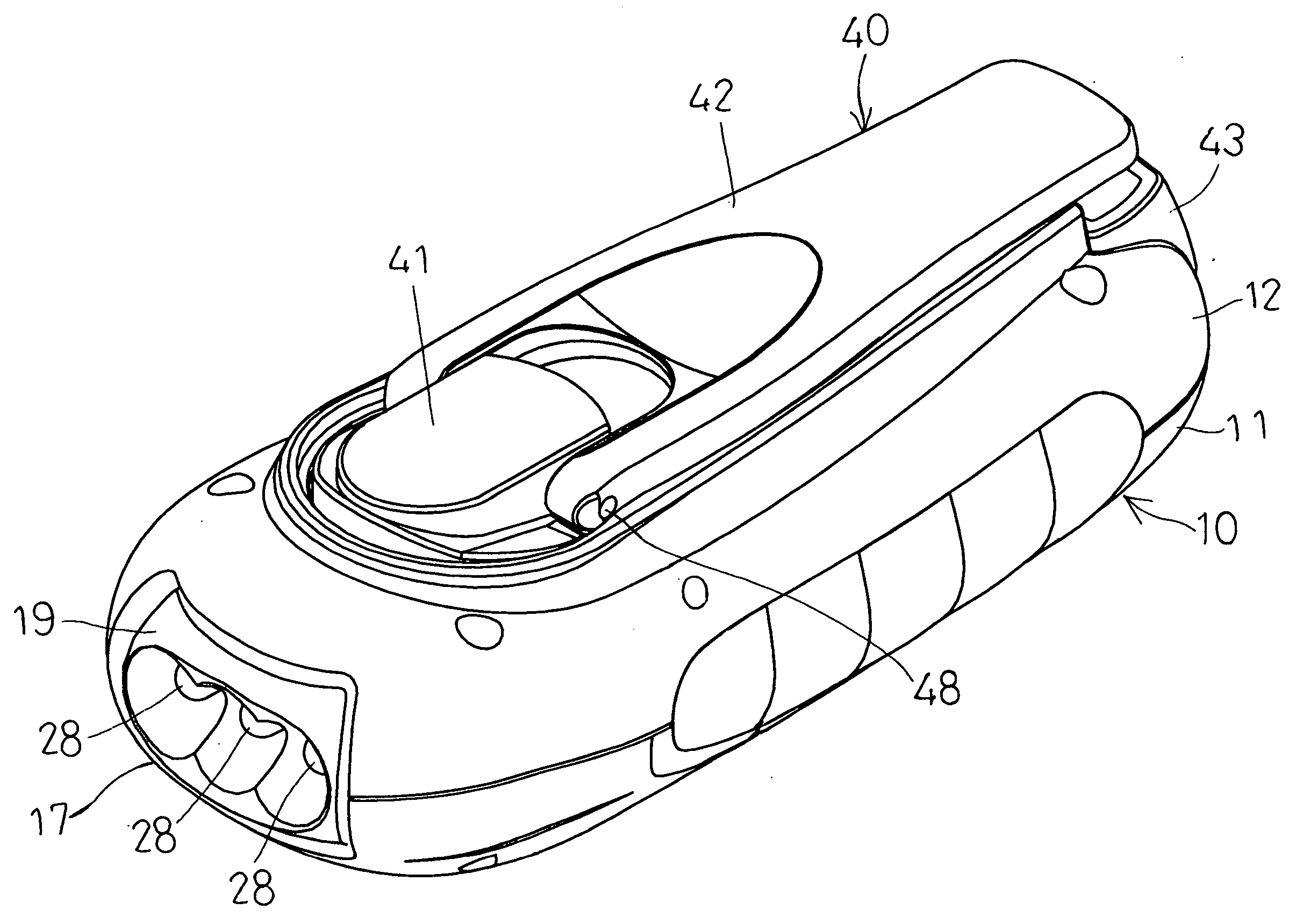
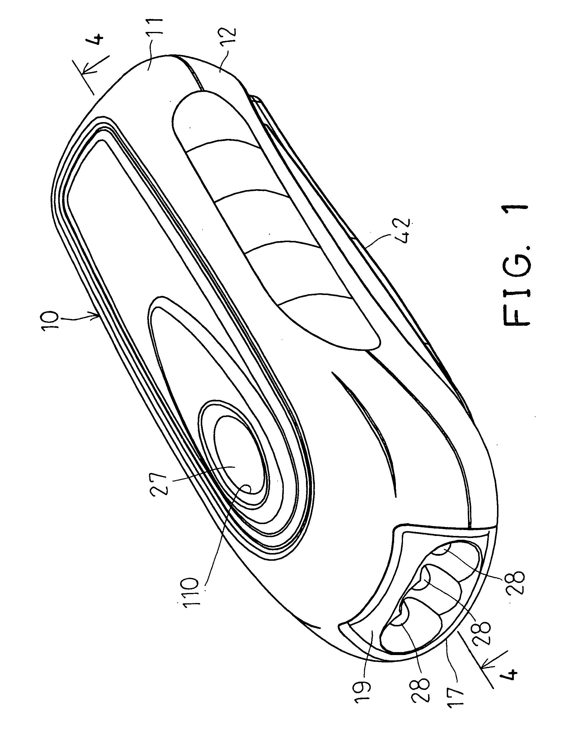
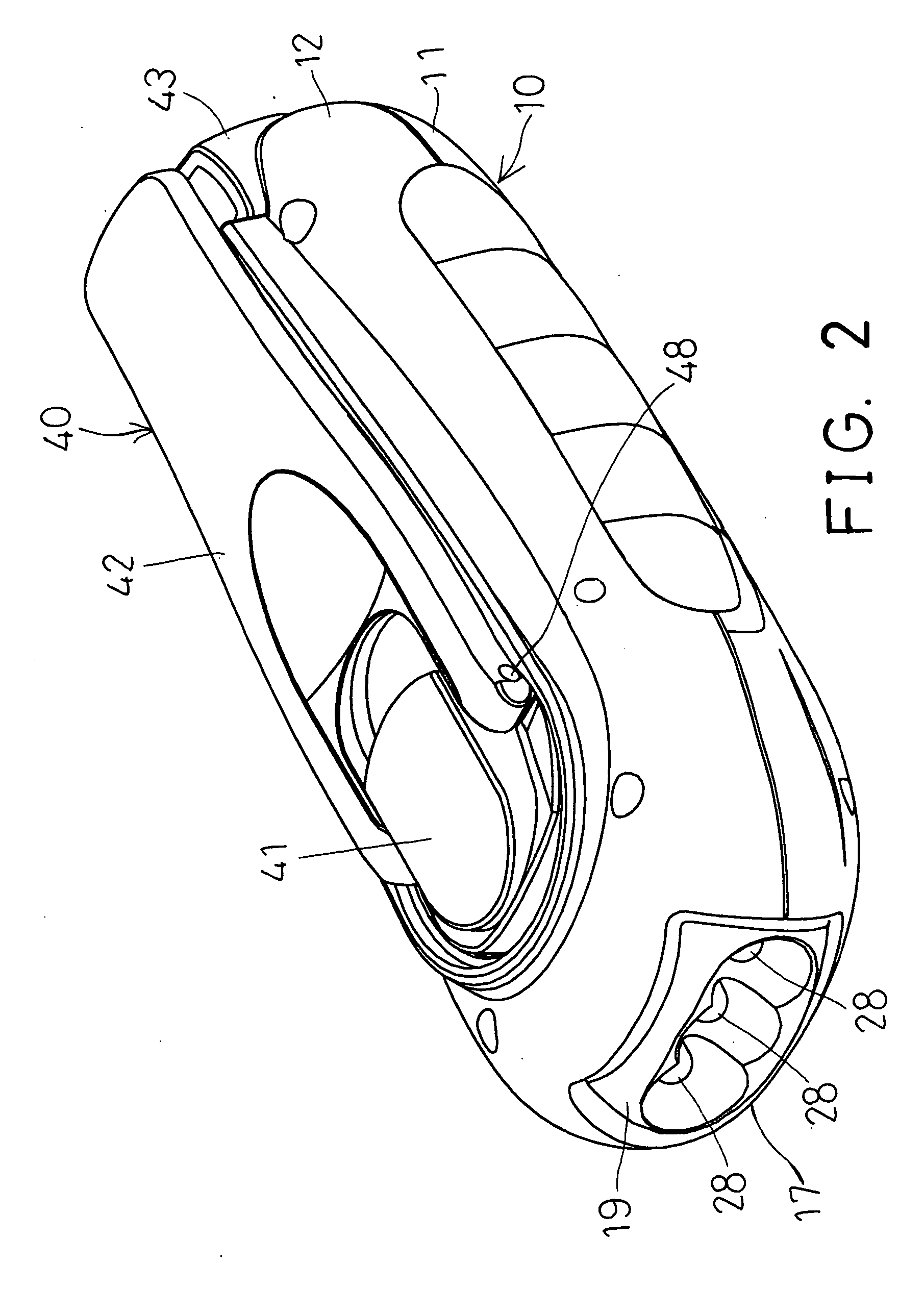
[0030] Referring to the drawings, and initially to FIGS. 1-4, a flashlight in accordance with the present invention comprises a housing 10 including such as a cover 11 attached or secured on top of a base 12 with such as fasteners 90. The cover 11 includes a peripheral rib 13 extended downwardly from the bottom peripheral portion thereof (FIGS. 3, 4) for engaging into a peripheral groove 14 of the base 12, for making a water tight seal between the cover 11 and the base 12.

[0031] The housing 10 includes a front opening 15 formed therein, to receive a lens or transparent hood 17 therein, and includes one or more flaps 16 extended therein to engage into the corresponding depressions 18 of the hood 17, and to stably secure the hood 17 in the front opening 15 of the housing 10. A reflective member 19 is received in the front portion of the housing 10, and / or engaged in the hood 17, and includes one or more holes 191 formed therein (FIGS. 4, 5).

[0032] A plate 20 is secured in the housin...


PUM


Abstract

A flashlight includes a circuit board received in a housing and having one or more light devices received in a front opening of the housing. One or more chargeable batteries are received in the housing and coupled to the light device for energizing the light device. An actuating device includes a follower rotatably attached to the housing, and a handle pivotally attached to the follower. A gearing device includes a gear coupled to actuate an electric generating device, to generate electric energy to energize the light device. A weight may be secured to the gear of the gearing device, to increase the moment of inertia of the gear, and to facilitate the rotational movement of the gear relative to the housing.

Description

BACKGROUND OF THE INVENTION [0001] 1. Field of the Invention [0002] The present invention relates to a flashlight, and more particularly to a flashlight having a manually operatable device to generate electric energy to energize the flashlight and / or to charge batteries of the flashlight. [0003] 2. Description of the Prior Art [0004] Typical flashlights comprise one or more batteries received in a housing, and coupled to one or more light bulbs, to energize the light bulbs, and to generate lights, such as flashlights. [0005] For example, U.S. Pat. No. 6,168,288 to Claire discloses one of the typical flashlights which also comprise one or more batteries coupled to one or more light bulbs to energize the light bulbs to generate lights. [0006] Most of the batteries are not chargeable, and should be discarded away after the electric energy of the batteries have been consumed. The other batteries may be re-chargeable, and may thus be used again and again. [0007] However, the typical re-c...

Claims


Application Information

Patent Timeline
Patent Type & Authority Applications(United States)
IPC IPC(8): F21L13/06
CPCF21Y2101/02F21L13/06F21Y2115/10
Inventor LEE, WEN SUNG
Owner LEH CHU ENTERPRISE
Why Eureka
Try Eureka