
Method of operating a Clos network

a technology of clos network and clos switches, applied in the field of clos network operation, can solve the problems of packet queue up, network performance degradation, packet queue up,

Inactive Publication Date: 2005-05-26
EMERSON NETWORK POWER EMBEDDED COMPUTING
View PDF8 Cites 15 Cited by
  • Summary
  • Abstract
  • Description
  • Claims
  • Application Information

AI Technical Summary

Problems solved by technology

Current switching topologies for network operations can cause a network to suffer performance degradation due to latency.
Significant delays from latency can result from queuing delays in network switches due to interference caused by competing traffic sources attempting to use the same network resources at the same time.
This can cause packets to queue up in one or more switches and delay the packet's delivery to its destination.
This increase in latency slows network response time and can result in lost packets and other disadvantageous network behavior.

Method used


Image

  • Method of operating a Clos network
  • Method of operating a Clos network
  • Method of operating a Clos network

Examples


Embodiment Construction

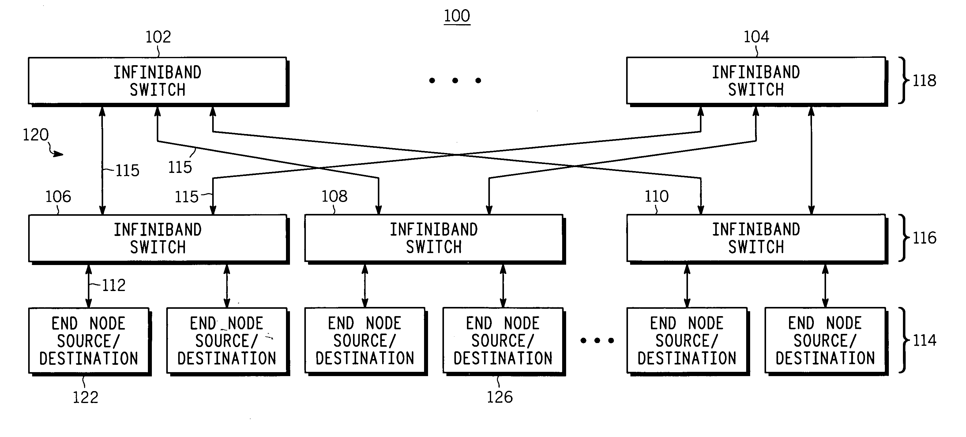
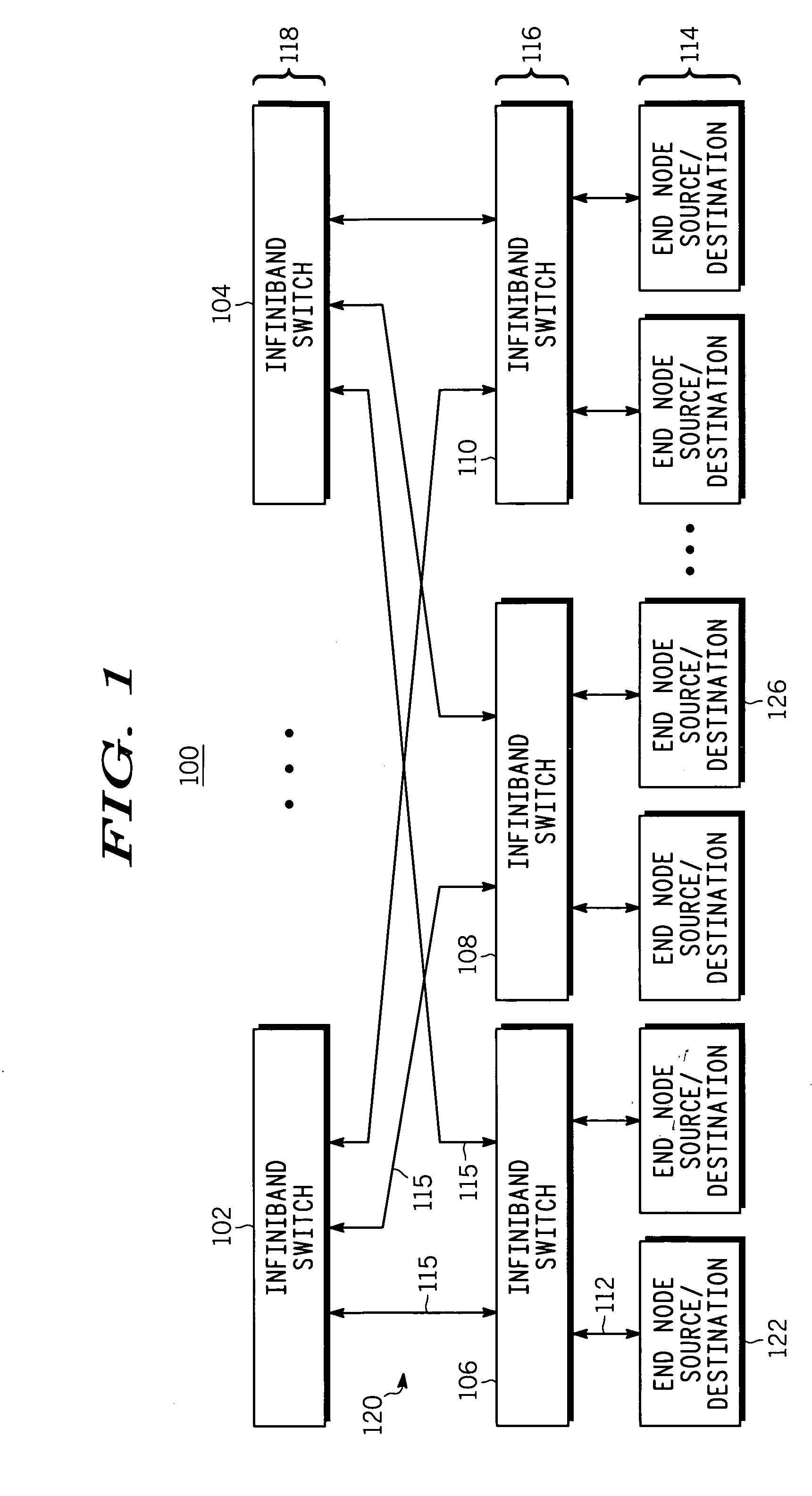
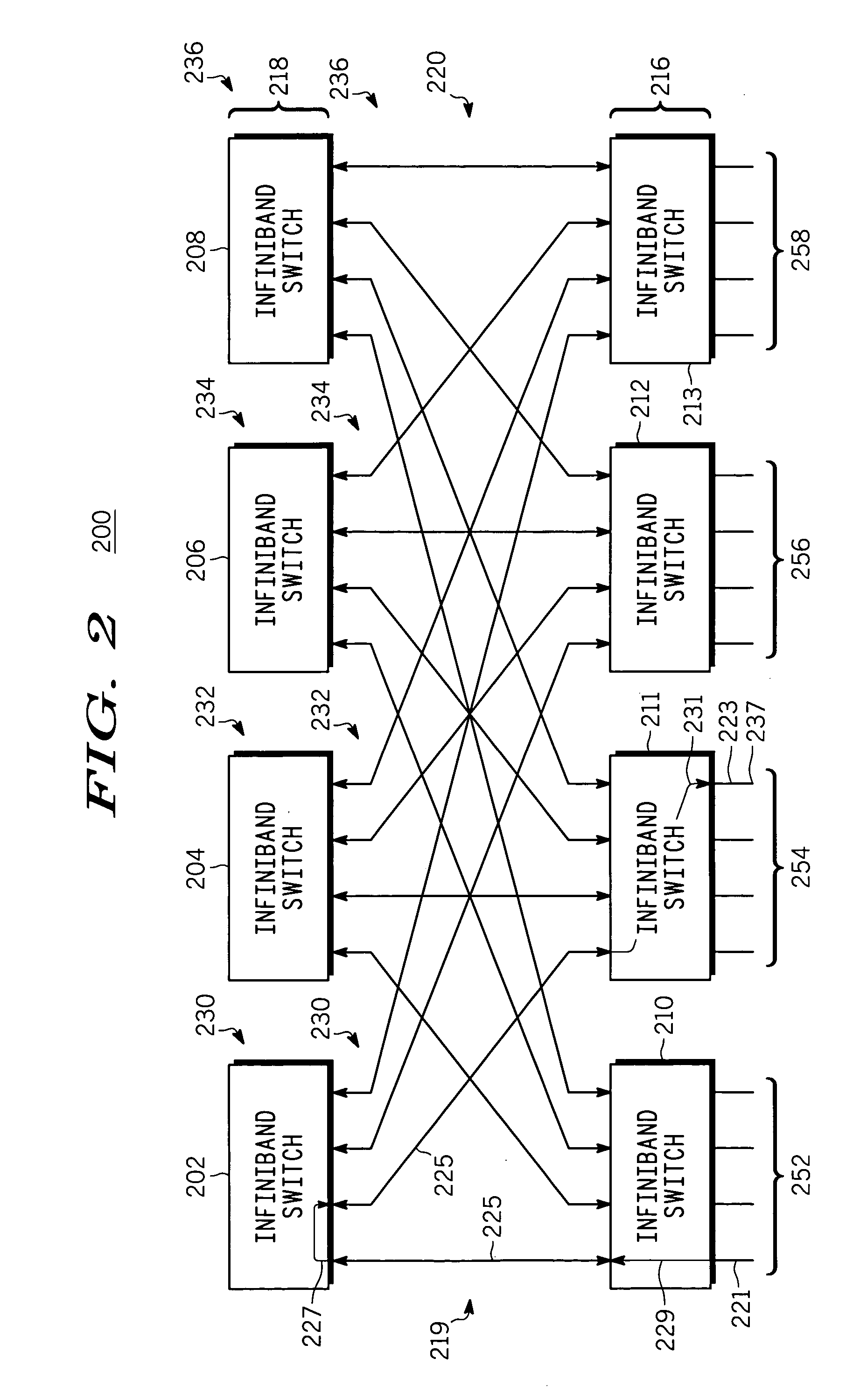
[0015] In the following detailed description of exemplary embodiments of the invention, reference is made to the accompanying drawings that illustrate specific exemplary embodiments in which the invention may be practiced. These embodiments are described in sufficient detail to enable those skilled in the art to practice the invention, but other embodiments may be utilized and logical, mechanical, electrical and other changes may be made without departing from the scope of the present invention. The following detailed description is, therefore, not to be taken in a limiting sense, and the scope of the present invention is defined only by the appended claims.

[0016] In the following description, numerous specific details are set forth to provide a thorough understanding of the invention. However, it is understood that the invention may be practiced without these specific details. In other instances, well-known circuits, structures and techniques have not been shown in detail in order...


PUM


Abstract

A method includes providing a plurality of InfiniBand switches (350, 318), wherein the plurality of InfiniBand switches are coupled to form a Clos network (320), providing a plurality of sources coupled to the Clos network, and providing a plurality of destinations coupled to the Clos network. Calculating a plurality of routing trees (330, 332, 334, 336) for the plurality of InfiniBand switches, and calculating a plurality of DLIDs (410) and a set of forwarding instructions (413) for each of the plurality of InfiniBand switches, where each of the plurality of DLIDs corresponds to one of the plurality of routing trees and one of the plurality of destinations. Populating a forwarding table (415) of each of the plurality of InfiniBand switches in the Clos network with the plurality of DLIDs and the set of forwarding instructions.

Description

RELATED CASES [0001] Related subject matter is disclosed in U.S. patent application entitled “INFINIBAND SWITCH OPERATING IN A CLOS NETWORK” having application Ser. No. ______ and filed on the same date herewith and assigned to the same assignee. [0002] Related subject matter is disclosed in U.S. patent application entitled “STRICTLY NON-INTERFERING NETWORK” having application Ser. No. ______ and filed on the same date herewith and assigned to the same assignee. [0003] Related subject matter is disclosed in U.S. patent application entitled “CONNECTION CONTROLLER” having application Ser. No. ______ and filed on the same date herewith and assigned to the same assignee.BACKGROUND OF THE INVENTION [0004] Current switching topologies for network operations can cause a network to suffer performance degradation due to latency. Significant delays from latency can result from queuing delays in network switches due to interference caused by competing traffic sources attempting to use the same...

Claims


Application Information

Patent Timeline
IPC IPC(8): H04L12/28H04L12/56
CPCH04L49/253H04L49/1515
Inventor STEWART, MARK ANDREW WHITTAKER
Owner EMERSON NETWORK POWER EMBEDDED COMPUTING
Learn More