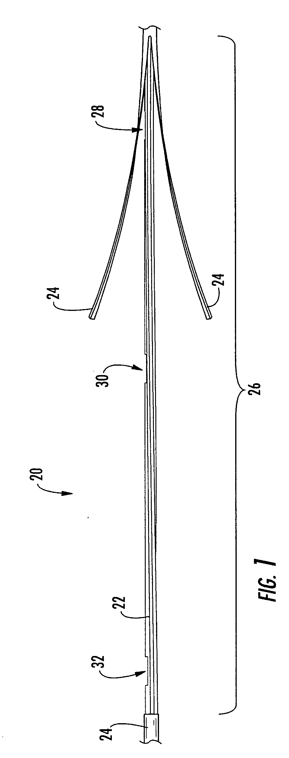
[0009] To achieve the foregoing and other objects, and in accordance with the purposes of the invention as embodied and broadly described herein, the present invention provides various embodiments of a factory-manufactured preterminated fiber optic distribution cable having at least one predetermined access location for providing access to at least one preterminated optical fiber. The factory preterminated distribution cable may be wound upon a cable reel and installed within a
conduit system having a
diameter of less than about 1.25 inches. The primary
advantage of this preterminated distribution cable over conventional cable systems is its small outer diameter, which lends itself to installation flexibility. Each access location has an outer diameter of less than 1.9 inches, and more preferably, less than about 1.25 inches, and presents at least one optical fiber for splicing a drop cable to the distribution cable after installation. A second
advantage of the present invention is the ability to use a variety of closure designs to protect the splices and to anchor the drop cables.
[0010] In one embodiment, the preterminated distribution cable comprises any fiber optic cable having at least one optical fiber disposed within a buffer tube. In order to achieve a low profile mid-span access in the factory, a section of the cable sheath is removed to
expose the at least one buffer tube within the distribution cable. Adjacent to the removed section, the cable sheath may be slit and flared back to
expose an additional length of the buffer tube. For each access location, the appropriate buffer tube may be accessed in at least two, and preferably three, places using a fiber access tool. Starting at the appropriate buffer tube access point, pre-selected optical fibers are accessed and severed. The remaining optical fibers remain intact and continue through the distribution cable. The pre-selected optical fibers may then be fished out of a second access point in the buffer tube, exposing a length of fiber. If necessary, the same optical fibers may then be fished out of the buffer tube a second time at a third access point, exposing a longer length of fiber.
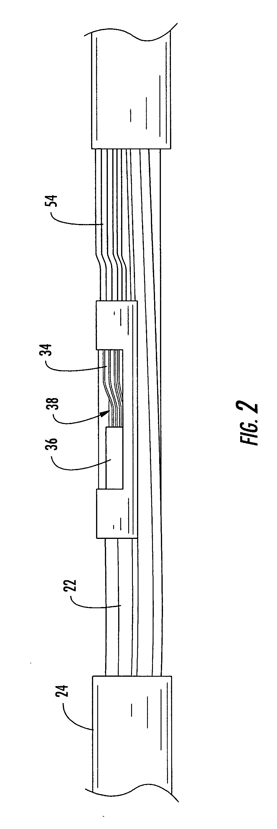
[0011] The exposed optical fiber length may then be routed through a transition piece and fed into one or more protective tubes secured to the transition piece. The transition piece may be secured to a structural member of the cable or to the buffer tube from which the optical fibers were removed at the location where the optical fibers exit the buffer tube. The transition piece is secured for anti-torque and may seal the optical fiber
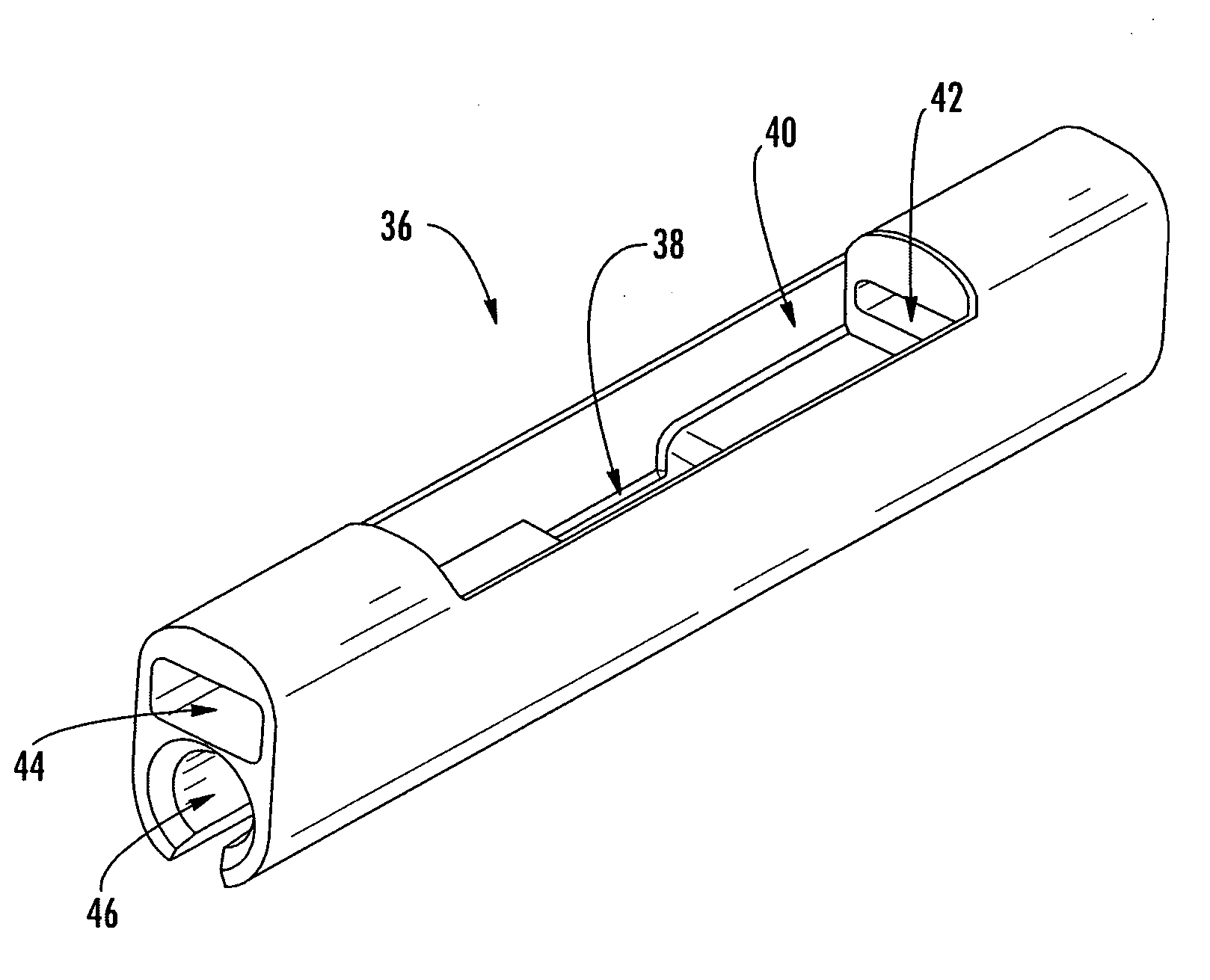
exit point. The one or two exposed access locations remaining on the buffer tube may also be sealed. The slit and flared cable sheath may be repositioned and covered using a heat shrinkable material, or with a self-fusing or elf-amalgamating tape. To protect the exposed region of cable sheath and provide an optical fiber guide channel, the protective tubes may be routed in a channel of a C-shaped molded member positioned and secured over the access location. A heat shrinkable material may be positioned over the access location with at least one ripcord disposed underneath. Once the distribution cable is installed, the at least one ripcord may be used to remove the outer layer of heat shrinkable material to
expose the C-shaped molded member. The C-shaped molded member may then be removed and the optical fibers presented for splicing.
[0012] In another embodiment, the present invention provides a preterminated fiber optic distribution cable having at least one predetermined access location for providing access to at least one preterminated optical fiber. The distribution cable comprises at least one buffer tube comprising at least one optical fiber, a buffer tube transition piece operable for transitioning the at least one optical fiber from the at least one buffer tube into at least one protective tube, a C-shaped molded member defining a longitudinally extending optical fiber guide channel operable for storing a length of the at least one preterminated optical fiber, and a protective means operable for protecting the at least one buffer tube, the buffer tube transition piece and the C-shaped molded member during installation of the preterminated fiber optic distribution cable. The preterminated distribution cable comprises an outer diameter less than 1.9 inches, and more preferably, less than about 1.25 inches. The preterminated distribution cable, the at least one buffer tube, the buffer tube transition piece and the C-shaped molded member are all sufficiently flexible to permit installation of the distribution cable through a conduit.
[0013] In a further embodiment, the present invention provides a method of mid-span accessing at least one optical fiber from a fiber optic distribution cable at a predetermined access location. The method comprises: (1) removing a predetermined length of a cable sheath to expose a predetermined length of at least one buffer tube; (2)
cutting one or more longitudinally extending slits into the cable sheath beginning at the downstream end of the exposed predetermined length of the at least one buffer tube; (3) flaring the
cut cable sheath to expose an additional length of the at least one buffer tube; (4)
cutting at least a first and a second access point on an appropriate buffer tube along the buffer
tube length about 10 to about 15 inches apart from one another; (5) severing at least one optical fiber at the first access point to produce at least one preterminated optical fiber; and (6)
fishing the at least one preterminated optical fiber out of the second access point to withdraw a first length of the preterminated optical fiber. The method may further comprise: (7)
fishing the at least one preterminated optical fiber out of a third access point to withdraw a second longer length of the preterminated optical fiber.
[0014] In a still further embodiment, the method further comprises repairing the flared and
cut cable sheath using a heat shrinkable material or using a self-fusing or self-amalgamating tape, transitioning the at least one preterminated optical fiber out of the appropriate buffer tube and into at least one protective tube via a buffer tube transition piece, maintaining the at least one preterminated optical fiber in a C-shaped molded member comprising a longitudinally extending optical fiber guide channel, and protecting and sealing the mid-span access with a heat shrinkable material.

