Gas-operated guns with demountable and interchangeable barrel sections and improved actuation cylinder construction

a technology of actuation cylinder and gas-operated guns, which is applied in the direction of weapons, weapon components, etc., can solve the problems of direct injection of gas into the working mechanism, serious dispersion of the resulting shots, etc., and achieve the effect of less expensive and greater accuracy

Inactive Publication Date: 2005-06-02
KNIGHT'S ARMAMENT COMPANY
View PDF10 Cites 78 Cited by
  • Summary
  • Abstract
  • Description
  • Claims
  • Application Information

AI Technical Summary

Benefits of technology

[0028] The size of the first radial port controls the volume of gas that is released to the gas system of the gun. Hence, each muzzle barrel portion can be selectively tuned by sizing its first radial port to provide the proper amount of gas to automatically cause the weapon to function at its desired cyclic rate based on the ammunition, silencer and length of the muzzle section selected by the user.
[0031] The operation gas is transmitted from the barrel to the actuation cylinder thru a flexible tube that effectively isolates the barrel from the mechanical system. In this way the invention provides a system that keeps the propellant gas out of the other working portions of the gun. The invention achieves this by attaching the barrel to the receiver in an un-conventional manner so the invention provides a gun that has the reliability and cleanliness of a gas piston forward of the bolt and bolt carrier with the accuracy associated with a free-floating barrel.
[0034] The barrel is mounted to the upper receiver with a combination of a bonded joint, four bolts and additionally supported by the guide rails for the bolt. In preferred embodiments, the barrel is bonded to the carbon-fiber upper receiver with an epoxy-based compound. When the bond joint is laid in, four machine screws pull the barrel into contact with the upper receiver keeping the bond joint as thin as possible. After the barrel joint has cured, the guide rails for the bolt and bolt carrier are bonded and riveted in place behind the barrel. The barrel mounting thus described provides a method of achieving a full floating barrel where foreword, beyond the chamber, the barrel does not contact the handguard or the gas system except with the gas tube. Accordingly, guns made in accordance with the invention have greater accuracy than guns whose gas system mounts to the barrel and the reaction forces from that interaction are mechanically taken by the barrel.
[0035] In accordance with a preferred embodiment of the invention, the gas is transmitted from the gun barrel to the actuation cylinder thru a “U” shaped tube that effectively isolates the barrel from the actuation cylinder. In this way, the invention provides a new system that keeps the propellant gas out of the other working portions of the weapon. This is attained in accordance with the invention with threaded fasteners and the guide rails for the mechanical system that is fastened to the receiver as well. The result is a weapon that has the reliability and cleanliness of a gas piston forward of the bolt and bolt carrier with the accuracy associated with a free-floating barrel.
[0036] Construction of guns in accordance with the invention will prove to be beneficial to gun users who want the ability to change the length of the barrel as well as those who want to tune the gun to work optimally with a particular round of ammunition or silencer. In the past what was required was having a dedicated upper receiver assembly for each of these instances. The volume required to store these front barrel extensions is dramatically less that than required for the storage of the complete upper receiver assembly. The front barrel extensions are also much less expensive than an entire new upper receiver assembly.

Problems solved by technology

This load on the barrel results in unwanted barrel movement at the time the projectile leaves the muzzle causing serious dispersion of the resulting shots.
The drawback to the M16 design is that it dumps that gas directly into the working mechanism that has historically been a detriment to reliable functioning.

Method used


Image

  • Gas-operated guns with demountable and interchangeable barrel sections and improved actuation cylinder construction
  • Gas-operated guns with demountable and interchangeable barrel sections and improved actuation cylinder construction
  • Gas-operated guns with demountable and interchangeable barrel sections and improved actuation cylinder construction

Examples


Embodiment Construction

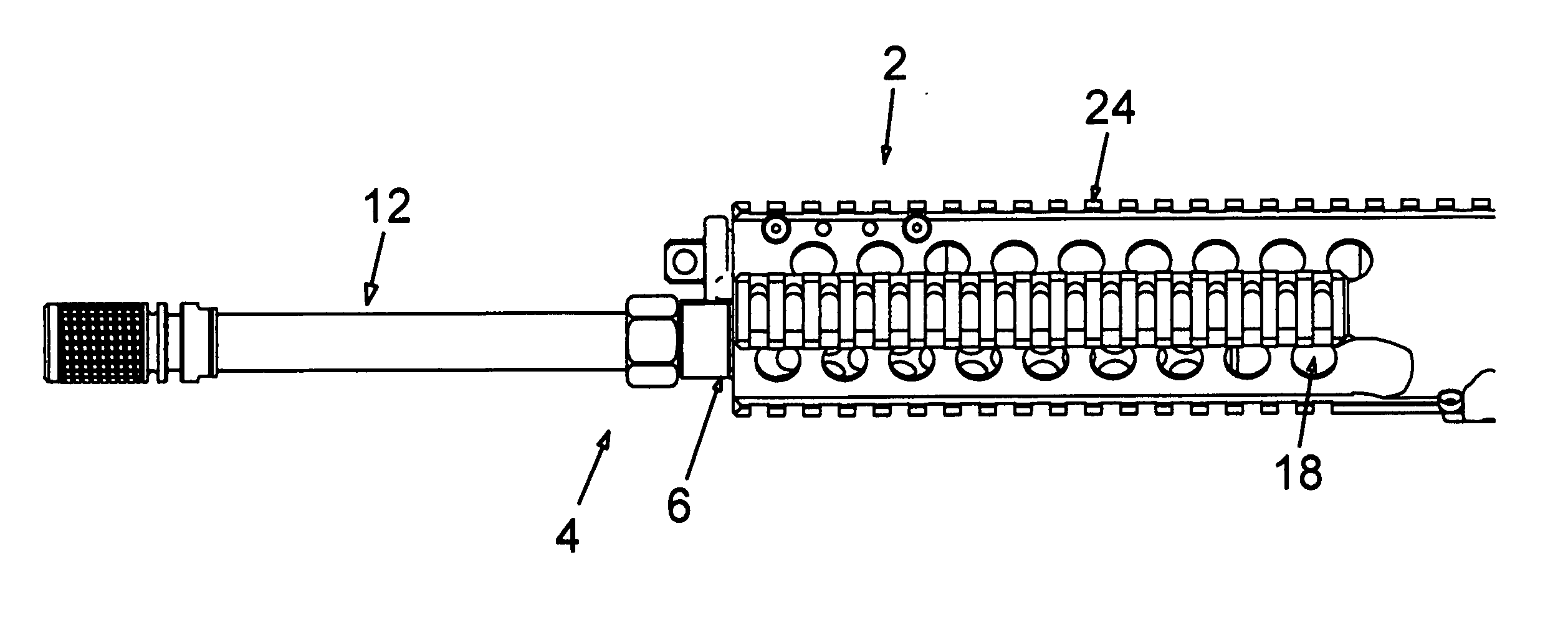
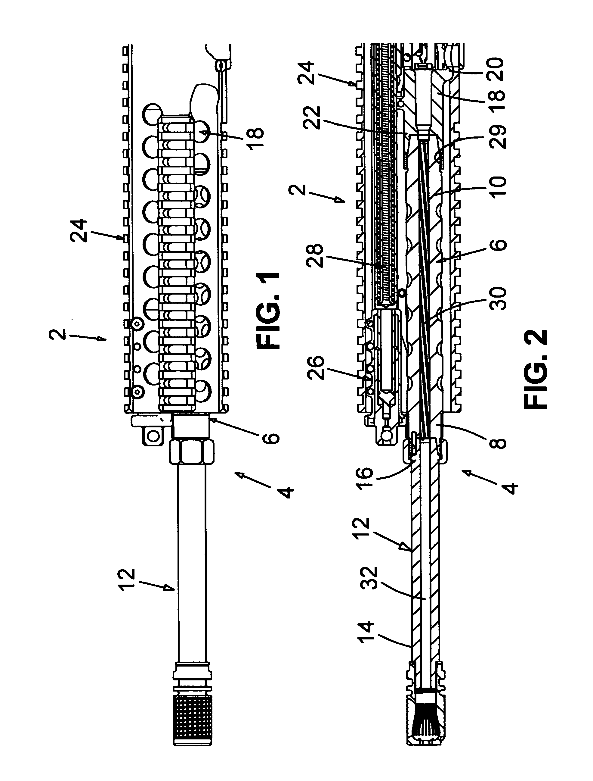
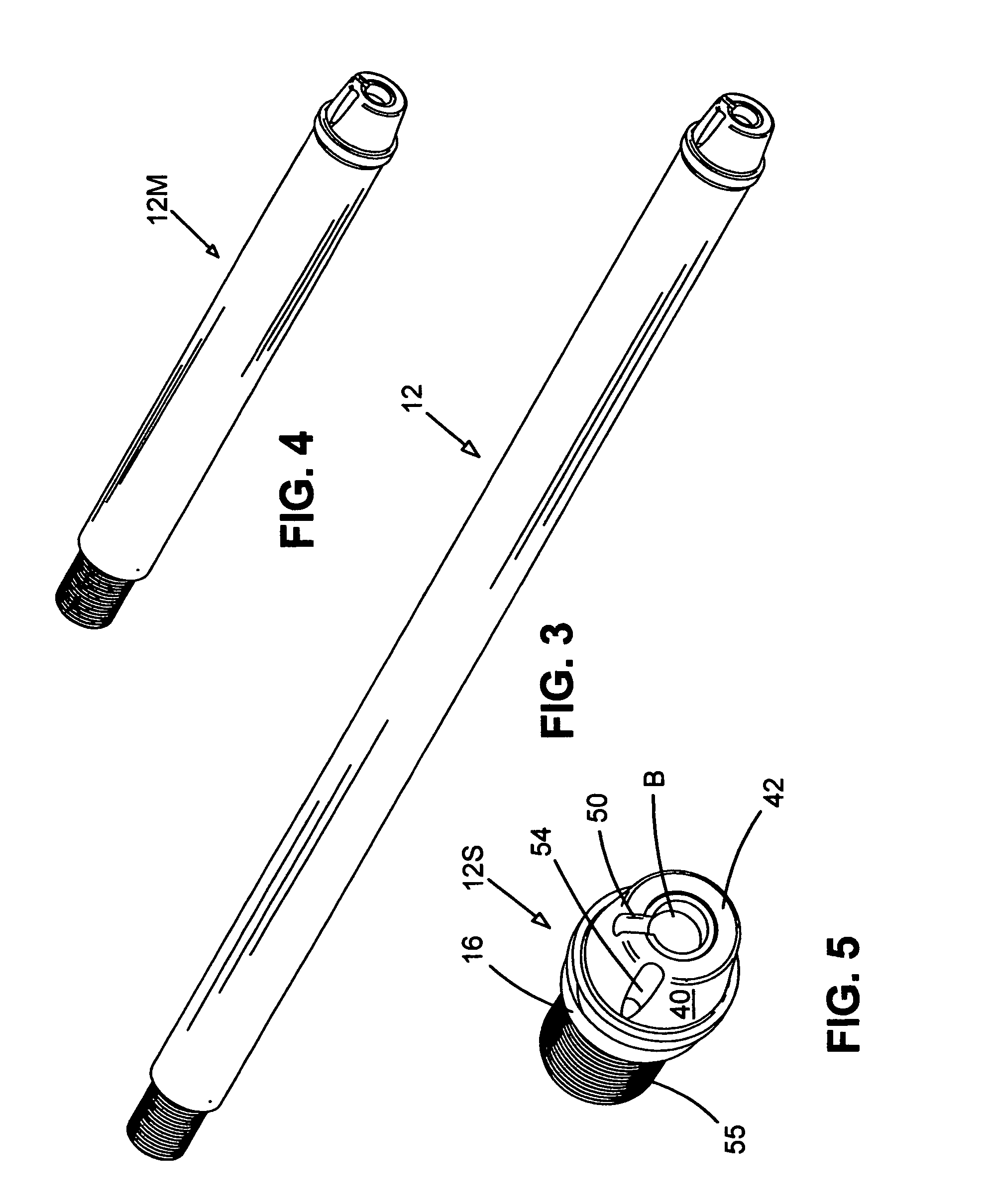
[0050] Referring in detail to the drawings beginning with FIGS. 1 & 2, the improved gun 2 of the invention comprises a bisectional barrel 4 having a breech section 6 defined by a breech front portion 8 and a breech rear portion 10 plus a demountable and interchangeable muzzle section 12 defined by a muzzle front portion 14 and a muzzle rear portion 16.

[0051] The gun 2 includes chamber 18 that is defined by a rear end 20 and front end 22. Chamber 18 is operatively connected by its front end 22 to breech rear portion 10.

[0052] The receiver 24 constitutes a major component of the gun 2. The rear end 20 of chamber 18 is mounted to receiver 24 to accept ammunition therein in known fashion of operation of M16 rifles. Also, an actuation cylinder 26 is mounted to the receiver 24 in manner explained further below.

[0053] Located within the receiver 24 there is a mechanical system 28, operated by the actuation cylinder 26, to perform in known manner the gun functions of unlocking, extractio...


PUM


Abstract

Gas-operated automatic and semi-automatic guns are improved by having a bisectional barrel with demountable and interchangeable muzzle sections wherein the breech section has a rifled bore and by having an actuation cylinder mounted to the receiver instead of the barrel. The muzzle sections are connected to the breech section via a tapered plug that locks into a tapered socket of the breech section. A port in the tapered plug joins with a port in the tapered socket to deliver gas from the barrel bore to the actuation cylinder and the tapered plug port in each interchangeable muzzle section is sized to provide automatic control of the proper amount of gas to cause the gun to function at its best rate based on the ammunition, silencer and length of the particular muzzle section selected by the user.

Description

BACKGROUND OF THE INVENTION [0001] 1. Field of the Invention [0002] This invention relates broadly to gas-operated automatic and semi-automatic guns, especially rifles. More particularly, it concerns such guns that comprise (a) a bisectional barrel with demountable and interchangeable muzzle sections and (b) an actuation cylinder mounted to the receiver instead of the barrel. [0003] 2. Description of the Prior Art [0004] There is a recognized need for guns that can easily change barrel length and that can facilitate the use of non-standard ammunitions in battle conditions. This invention provides improvements in gun construction that supply these needs with greater weapon reliability and adaptability than has been attainable with prior known guns. [0005] It is known to construct guns with bisectional barrels in which the breech section bore is smooth and the muzzle section bore is rifled. Thus, U.S. Pat. Nos. 4,546,564 and 4,660,312 disclose such bisectional barrels in which the rea...

Claims


Application Information

Patent Timeline
Patent Type & Authority Applications(United States)
IPC IPC(8): F41A21/00
CPCF41A21/00F41A5/26F41A5/18
Inventor OLSON, DOUGLAS D.
Owner KNIGHT'S ARMAMENT COMPANY
Why Eureka
Try Eureka