Inflator

Active Publication Date: 2005-06-02
TOYODA GOSEI CO LTD
View PDF16 Cites 14 Cited by
  • Summary
  • Abstract
  • Description
  • Claims
  • Application Information

AI Technical Summary

Benefits of technology

[0022] Moreover, it is desired that the first support portion is located substantially in an axial middle position in the retainer. With this construction, the first support portion is proximate a middle position between the fastening portion and the second support portion, and therefore, the retainer holds the body well-balancedly.
[0023] Moreover, it is desired that the first support portion and the second support portion are beads that are made by pressing a sheet metal forming the retainer. With this construction, the first and second sup

Problems solved by technology

When the airbag is folded, accordingly, the work has to be done in an environment considering malfunction of the inflator inserted in the airbag, which complicates the folding work of the airbag.
However, the mounting means such as bolts for mounting the airbag to the mounting position are protruded from the retainer of the inflator, and the mounting means obstruct insertion of the inflator in the airbag af

Method used


Image

  • Inflator
  • Inflator
  • Inflator

Examples


Example

[0047] Preferred embodiments of the present invention are described below with reference to the accompanying drawings. However, the invention is not limited to the embodiments disclosed herein. All modifications within the appended claims and equivalents relative thereto are intended to be encompassed in the scope of the claims.

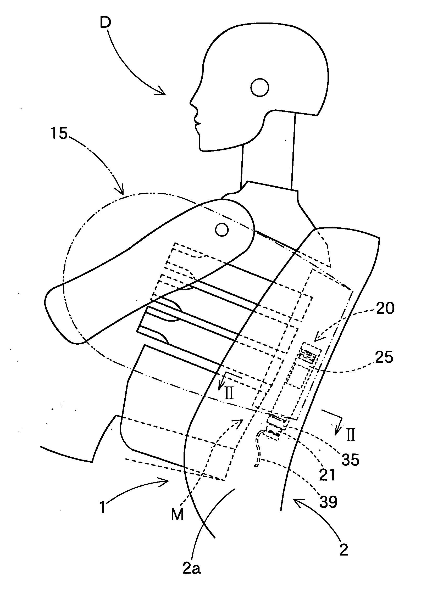
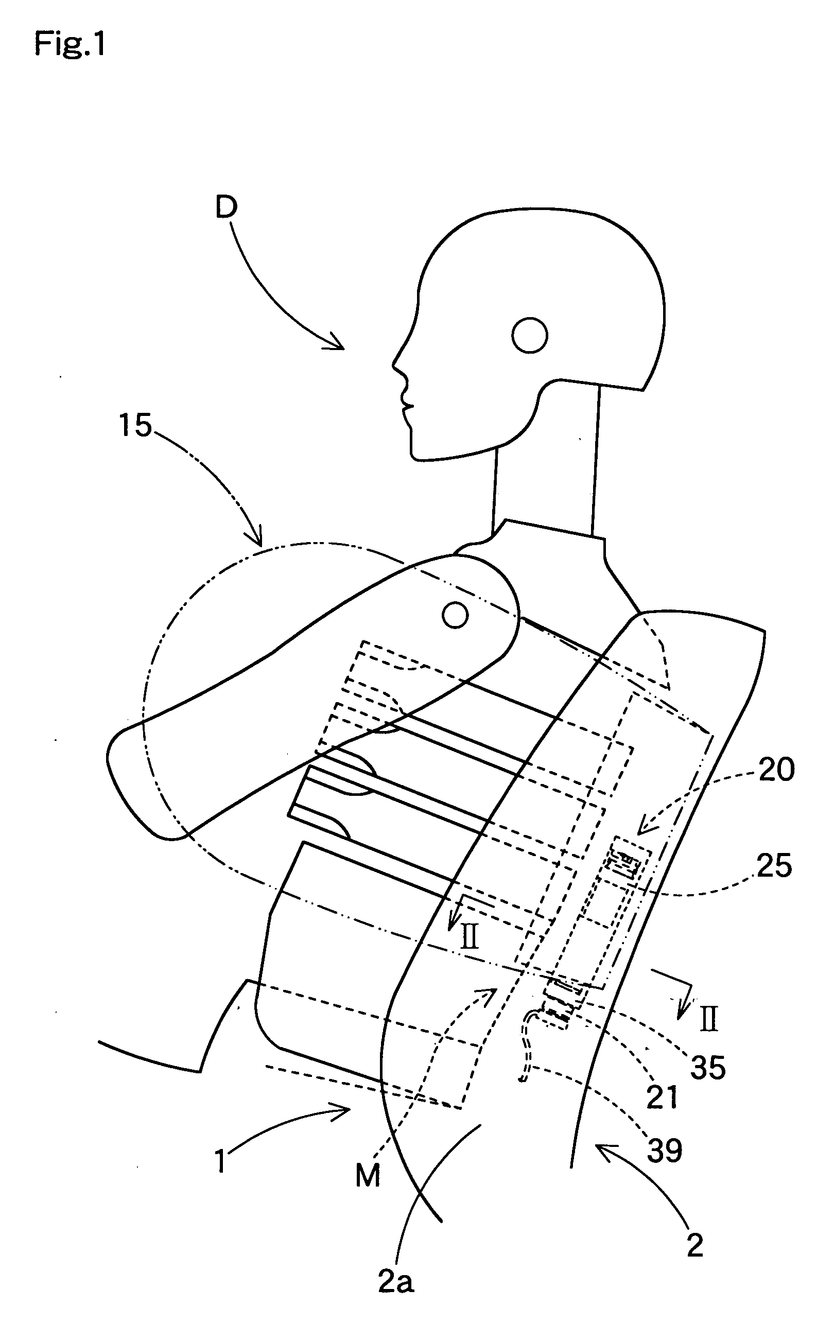
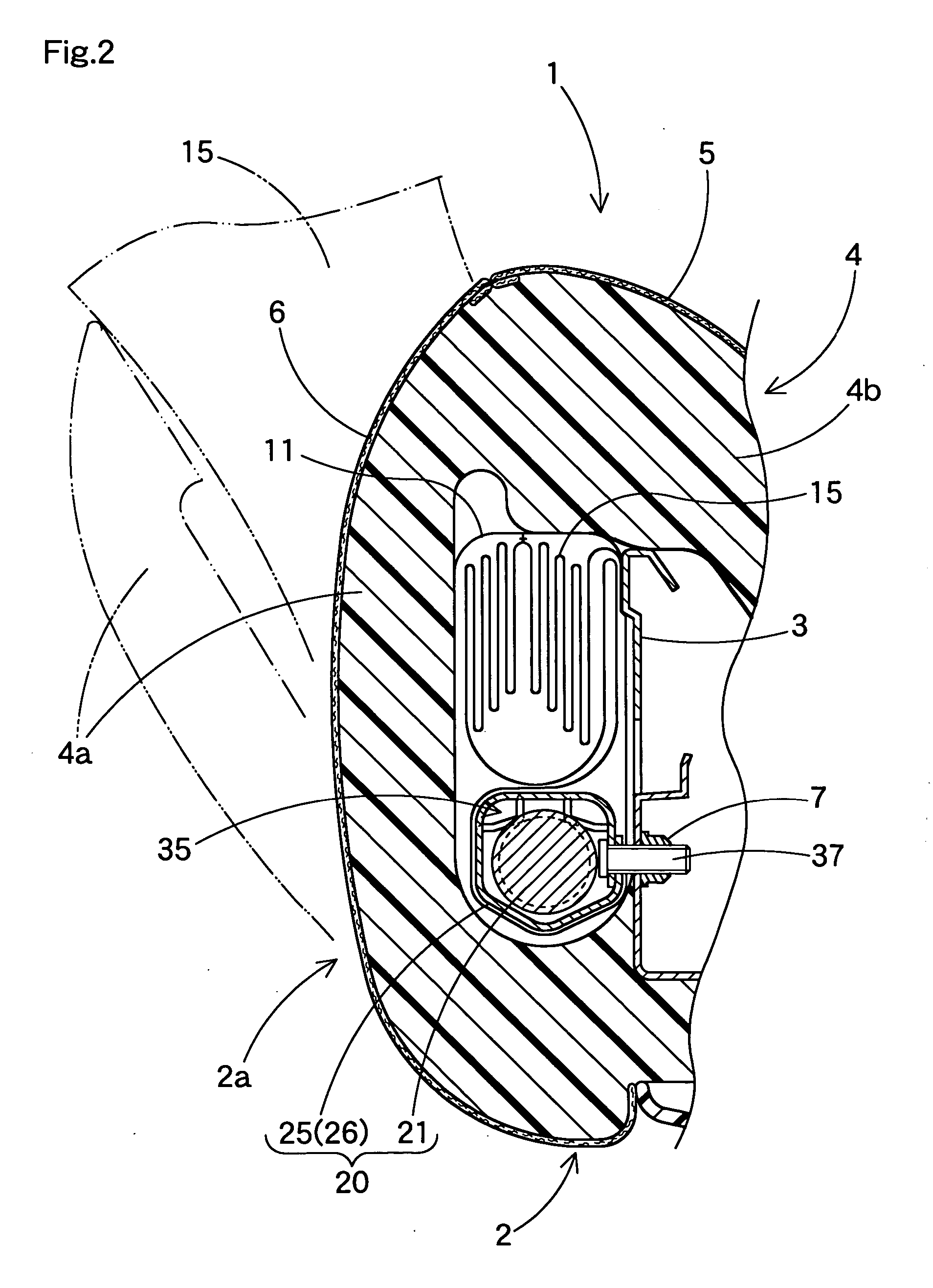
[0048]FIGS. 1 and 2 illustrate an embodiment of the inflator 20 of the present invention. The inflator 20 is part of a side impact airbag device M located in an exterior side 2a of a seat back portion 2 of a seat 1.

[0049] The seat back portion 2 includes a seat frame 3 which is arranged generally vertically, and the side impact airbag device M is secured to the seat frame 3 by a later-described retainer 25 by bolts 37 and nuts 7. In FIG. 2, a member with reference numeral 4 is a cushion, and members with reference numerals5 and 6 are surface skins made of decoration fabric or the like. A left edge portion 4a of the cushion 4 covers the side impact airbag de...


PUM


Abstract

An inflator according to the present invention is located inside an airbag of airbag device for supplying inflation gas. The inflator includes a substantially cylindrical body for generating inflation gas, and a substantially tubular retainer made of sheet metal to be mounted around the body for holding the body by fastening a fastening portion. The retainer includes mounting bolts for mounting the airbag to a predetermined mounting position. The retainer includes a fastening portion, a first support portion and a second support portion which are arranged in order along axial direction of the body to abut against a circumference of the body. The fastening portion and the second support portion are located in a substantially opposite area from the first support portion in the circumference of the body based on a center of a cross section of the body taken perpendicularly to the axial direction of the body as the retainer holds the body. In the inflator of the present invention, the inflator body is easily assembled with the retainer disposed inside a folded airbag, which facilitates a folding work of the airbag.

Description

[0001] The present application claims priority from Japanese Patent Application No. 2003-392316 of Mabuchi, filed on Nov. 21, 2003, and Japanese Patent Application No. 2004-218667 of Mabuchi et al., filed on Jul. 27, 2004, the disclosures of which are hereby incorporated into the present application by reference. BACKGROUND OF THE INVENTION [0002] 1. Field of the Invention [0003] The present invention relates to an inflator for supplying inflation gas to an airbag of airbag device for automobile which is used in an inserted state in the airbag. [0004] 2. Description of Related Art [0005] Japanese Patent Laid-Open No. 2001-171468 discloses an inflator for a side impact airbag device mountable on a vehicle seat. The inflator is inserted within an airbag for supplying the airbag with inflation gas. The inflator includes a substantially cylindrical body for generating inflation gas, and a substantially tubular retainer made of sheet metal and mounted around the body for holding the body...

Claims


Application Information

Patent Timeline
IPC IPC(8): B60R21/16B60R21/20B60R21/207B60R21/217B60R21/26
CPCB60R21/207B60R21/261B60R21/26B60R21/231
Inventor MABUCHI, SATOSHISATO, EIJI
Owner TOYODA GOSEI CO LTD
Why Eureka
Try Eureka