Method of manufacturing lead block for rotary connector

Inactive Publication Date: 2009-06-25
ALPS ALPINE CO LTD
View PDF5 Cites 4 Cited by
  • Summary
  • Abstract
  • Description
  • Claims
  • Application Information

AI Technical Summary

Benefits of technology

[0013]In this way, the connection terminal connecting body, which includes the group of the connection terminals and the connection parts, is previously formed. The group of the connection terminals has a predetermined shape where the second connection terminal portions are arranged on parallel planes. The connection terminals are connected to each other by the connection parts. Accordingly, after the base body made of an insulating resin is molded while the connection termina

Problems solved by technology

However, if the number of circuits increases, a longitudinal dimension excessively increases in the case of a lead block where connection terminal groups used for the connection of an external connector or an external lead are arranged in one line, which causes interference in mounting the lead block on the housing.
Accordingly, there are problems in that the numbers of processes for manufacturing a desired lead block increases and the cost of a mold increases.
Meanwhile, as described in U.S. Pat. No. 6,733,300, in the case of the lead block where the body pa

Method used


Image

  • Method of manufacturing lead block for rotary connector
  • Method of manufacturing lead block for rotary connector
  • Method of manufacturing lead block for rotary connector

Examples


first embodiment

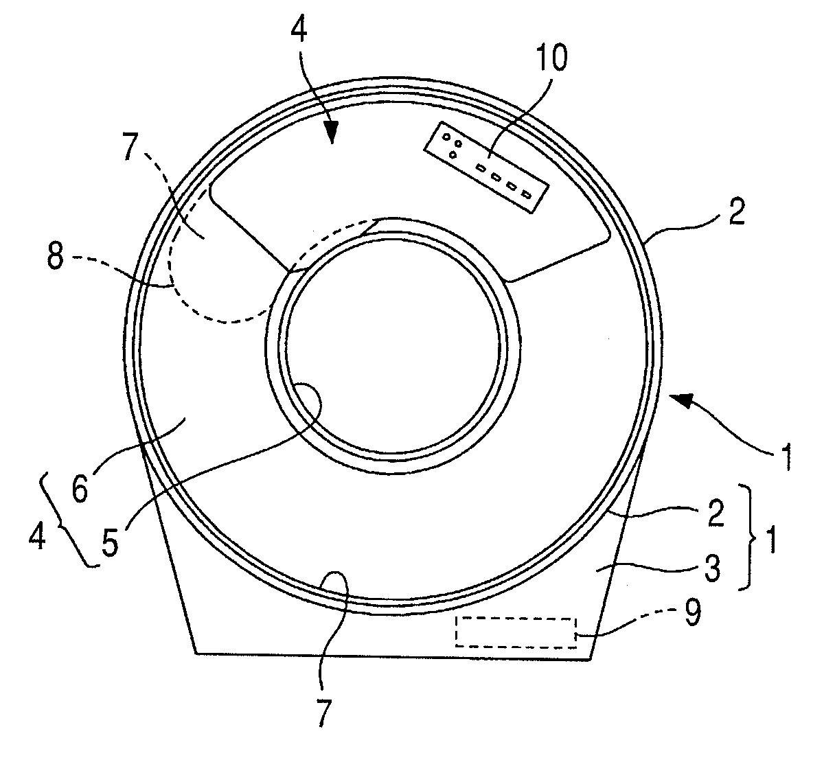
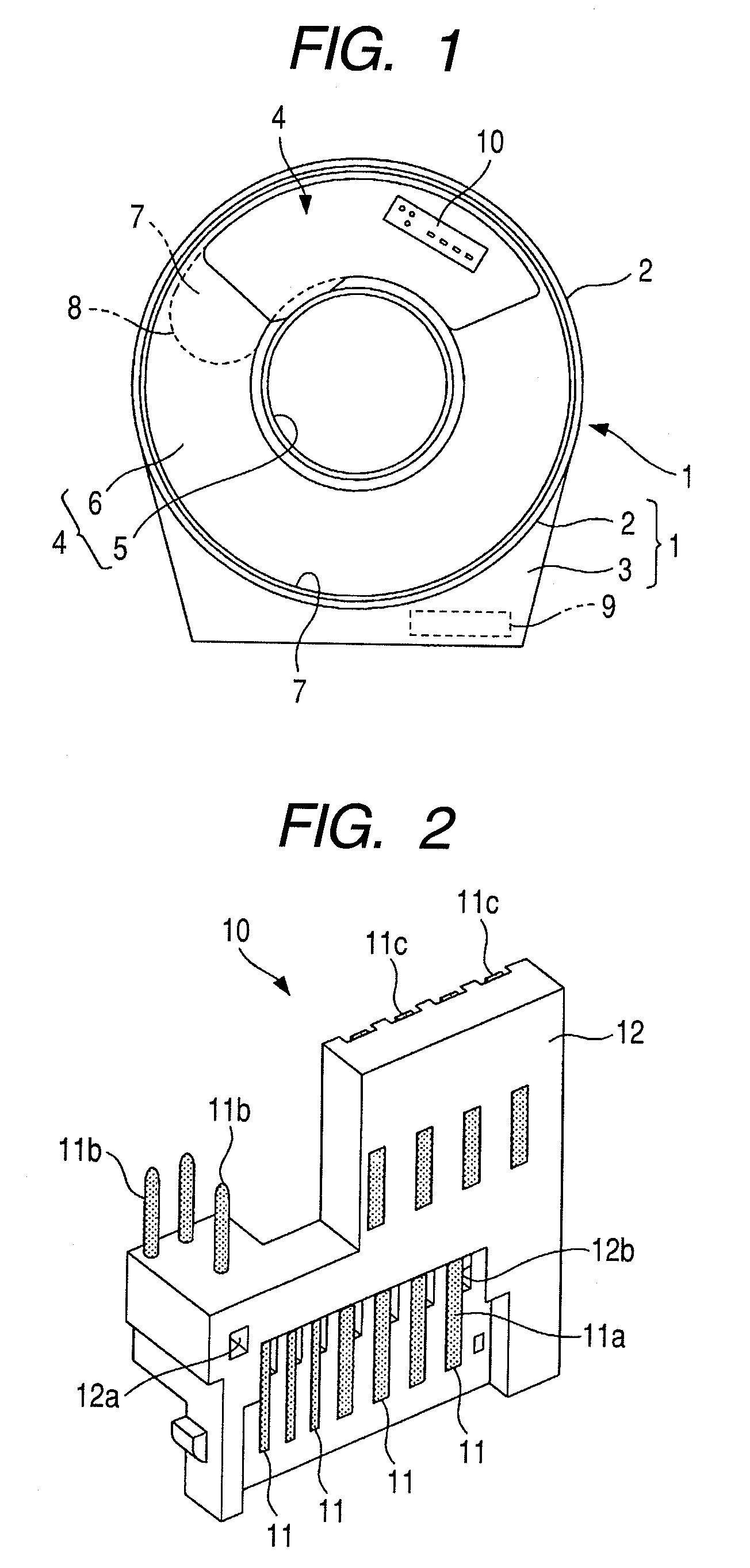
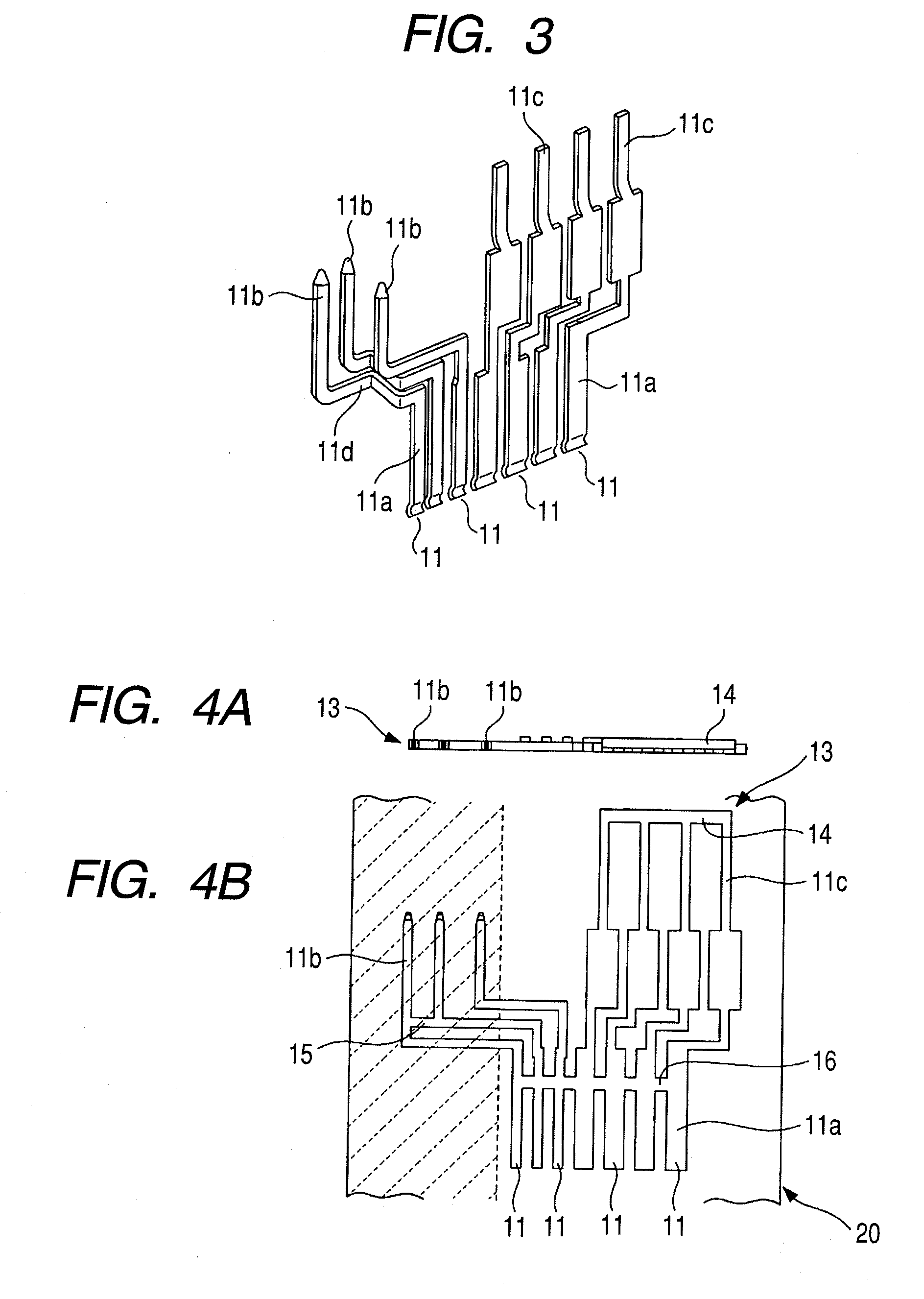
[0025]Embodiments of the invention will be described with reference to drawings. FIG. 1 is a plan view of a rotary connector including a lead block for a rotary connector according to the invention. FIG. 2 is a perspective view of the lead block shown in FIG. 1. FIG. 3 is a perspective view of connection terminals of the lead block shown in FIG. 2. FIGS. 4 to 7 are views illustrating processes for manufacturing the lead block shown in FIG. 2.

[0026]As shown in FIG. 1, a rotary connector, which includes a lead block for a rotary connector according to this embodiment, mainly includes a stationary housing 1 that includes an outer cylindrical part 2 and a bottom wall 3, a movable housing 4 that includes an inner cylindrical part 5 and a top plate 6, a flexible cable 8 that is received in an annular space 7 formed between the housings 1 and 4 so as to be wound and unwound, a movable body (not shown) that is disposed in the space 7 so as to be moved in a circumferential direction and wind...

second embodiment

[0037]FIGS. 8 to 11 are views illustrating processes for manufacturing a lead block according to the invention. Since portions corresponding to those of FIGS. 4 to 6 are indicated by the same reference numerals, the repeated descriptions thereof will be omitted. FIGS. 8A, 9A, and 10A are plan views, and FIGS. 8B, 9B, 10B, and 11 are front views.

[0038]The second embodiment is different from the first embodiment in that a lead block 17 shown in FIG. 11 includes connection terminals 11 of which the total number is eight and four connection terminals 11 of the connection terminals have pin-shaped second connection terminal portions 11b connected to an external connector.

[0039]A method of manufacturing the lead block 17 is basically the same as the method according to the first embodiment. First, a lead blank 18, which has the shape of a substantially flat plate as shown in FIG. 8, is formed by performing blanking on a metal plate of which a part is plated. Further, as shown in FIG. 9, L...


PUM


Abstract

There is provided a method of manufacturing a lead block for a rotary connector. The rotary connector includes stationary and movable housings, a flexible cable, and lead blocks. The method includes forming a connection terminal connecting body, where connection terminals are connected to each other by connection parts, by performing blanking and bending on a metal plate, forming a base body made of an insulating resin by performing insert molding so that the connection terminal connecting body is embedded in the base body except for at least of the connection parts and first and second connection terminal portions, and making the connection terminals be electrically isolated from each other by removing predetermined portions of the connection parts. The second connection terminal portions of the connection terminals are arranged on parallel planes.

Description

CLAIM OF PRIORITY [0001]The present invention claims the benefit of and contains subject matter related to Japanese Patent Application No. 2007-332620 filed in the Japanese Patent Office on Dec. 25, 2007, the entire contents of which is incorporated herein by reference.BACKGROUND[0002]1. Technical Field[0003]The present invention relates to a method of manufacturing a lead block for a rotary connector assembled into a rotary connector that is assembled in a steering device for a vehicle and electrically connects an electrical device disposed on a stator with an electrical device disposed on a rotor.[0004]2. Related Art[0005]This kind of rotary connector mainly includes stationary and movable housings that are disposed concentrically with each other and connected to each other so as to freely rotate relative to each other, a flexible cable that is received in a space formed between the pair of housings, and lead blocks that are mounted at predetermined positions on the housings. When...

Claims


Application Information

Patent Timeline
IPC IPC(8): H01R43/16
CPCH01R35/025H01R43/16Y10T29/49204Y10T29/49222H01R43/24
Inventor YAJIMA, KOICHI
Owner ALPS ALPINE CO LTD
Why Eureka
Try Eureka