

Data receiving device
- Summary
- Abstract
- Description
- Claims
- Application Information
AI Technical Summary
Benefits of technology
Problems solved by technology
Method used
Image

Examples
first embodiment
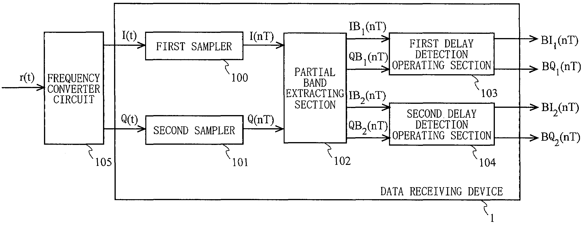
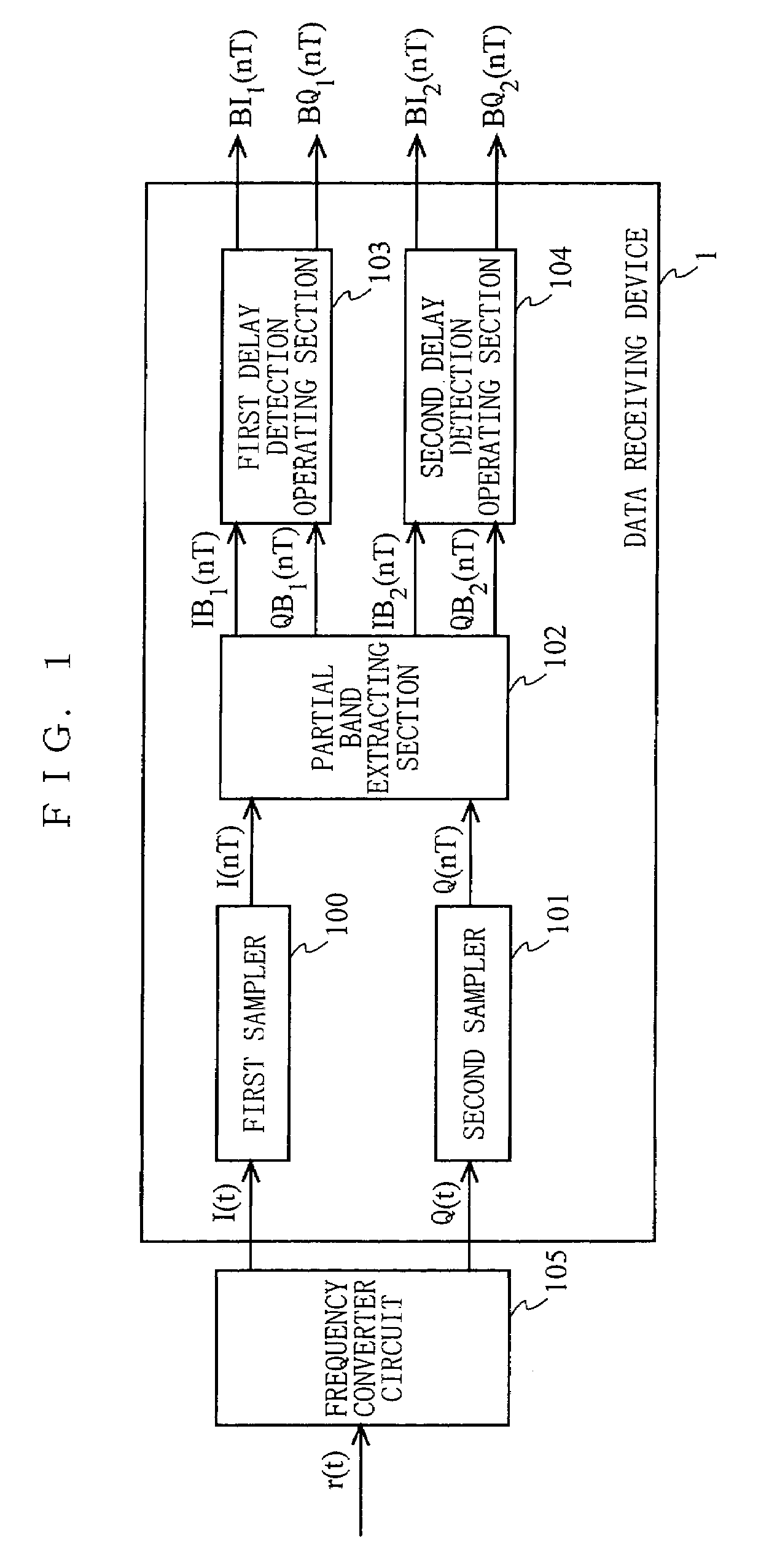
[0077]FIG. 1 is an illustration showing the configuration of a data receiving device 1 according to the first embodiment of the present invention. The data receiving device 1 extracts at least one partial band signal from frequency components of a received phase-modulated signal, and then obtains a detection signal through delay detection. In FIG. 1, the data receiving device 1 includes a first sampler 100, a second sampler 101, a partial band extracting section 102, a first delay detection operating section 103, and a second delay detection operating section 104. The first sampler 100 and the second sampler 101 have connected prior thereto a frequency converter circuit 105.
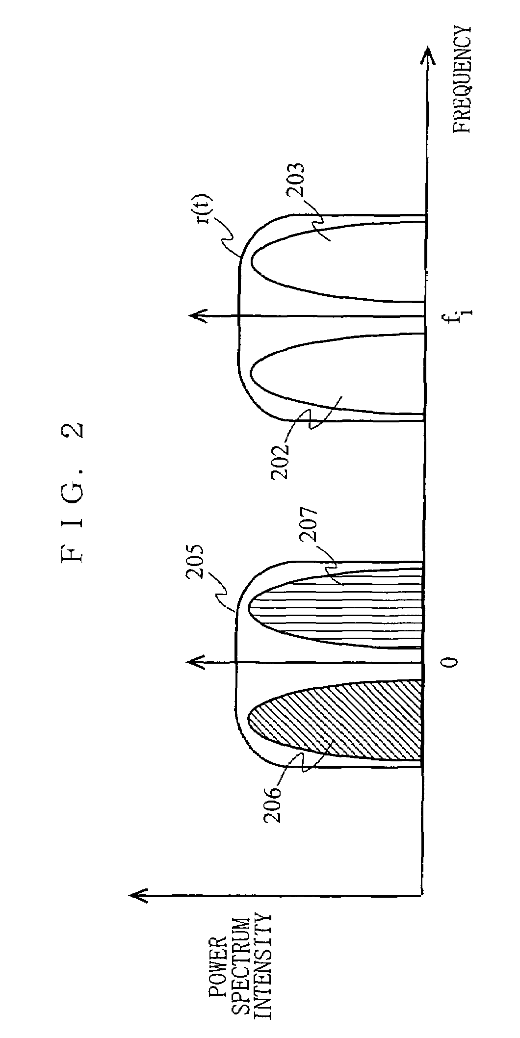
[0078]FIG. 2 is an illustration showing signal spectra for broadly describing how an in-phase component I(t) and a quadrature component Q(t) of a complex baseband signal are obtained from a high-frequency signal supplied to the frequency converter circuit 105. With reference to FIGS. 1 and 2, the operations of th...
second embodiment
[0115]In the first embodiment, a high-frequency modulated signal including a plurality of partial band signals is supplied to the data receiving device. In a second embodiment, a data receiving device which is supplied with a single modulated signal is described.
[0116]FIG. 7 is an illustration showing the configuration of a data receiving device 2 according to the second embodiment of the present invention. In FIG. 7, the data receiving device 2 includes a first sampler 500, a second sampler 501, a partial band extracting section 502, and a delay detection operating section 503. The first sampler 500 and the second sampler 501 have connected prior thereto a frequency converter circuit 505. The delay detection operating section 503 has connected subsequent thereto a decision circuit (not shown).
[0117]The operations of the frequency converter circuit 505 and the data receiving device are described below. The first sampler 500 samples an in-phase component I(t) of a complex baseband si...
third embodiment
[0126]The structure of the partial band extracting section 102 in the data receiving device 1 according to the first embodiment is described below in detail. First, a theory constituting grounds for the structure of the partial band extracting section 102 is described by using equations.
[0127]Now, it is assumed that two partial band signals to be extracted have center frequencies equally distanced apart from 0 by 1 MHz. Also, a transmission function of the complex filter for extracting the partial band complex signal 206 is represented as Hb(nT). In this case, the transmission function of the complex filter for extracting the partial band complex signal 206 illustrated in FIG. 2 is a complex conjugate of Hb(nT). As a result, S2(nT) representing the partial band complex signal 207 and S1(nT) representing the partial band complex signal 206 are expressed by the following Equation 9 and Equation 10, respectively.
[0128]S2(nT)=S(nT)*Hb(nT)={Re(S(nT))+jIm(S(nT))}*{Re(Hb(nT)+j...
PUM
 Abstract
Description
Claims
Application Information