Apparatus for symbol timing detection for wireless communication system
a technology of wireless communication system and antenna, applied in the direction of phase-modulated carrier system, synchronisation signal speed/phase control, amplitude demodulation, etc., can solve the problems of deterioration of performance and inaccurate signals after analog-to-digital converters, and achieve the effect of reducing complexity and reducing performan
- Summary
- Abstract
- Description
- Claims
- Application Information
AI Technical Summary
Benefits of technology
Problems solved by technology
Method used
Image
Examples
first embodiment
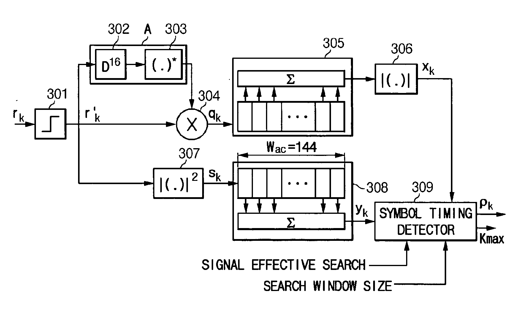
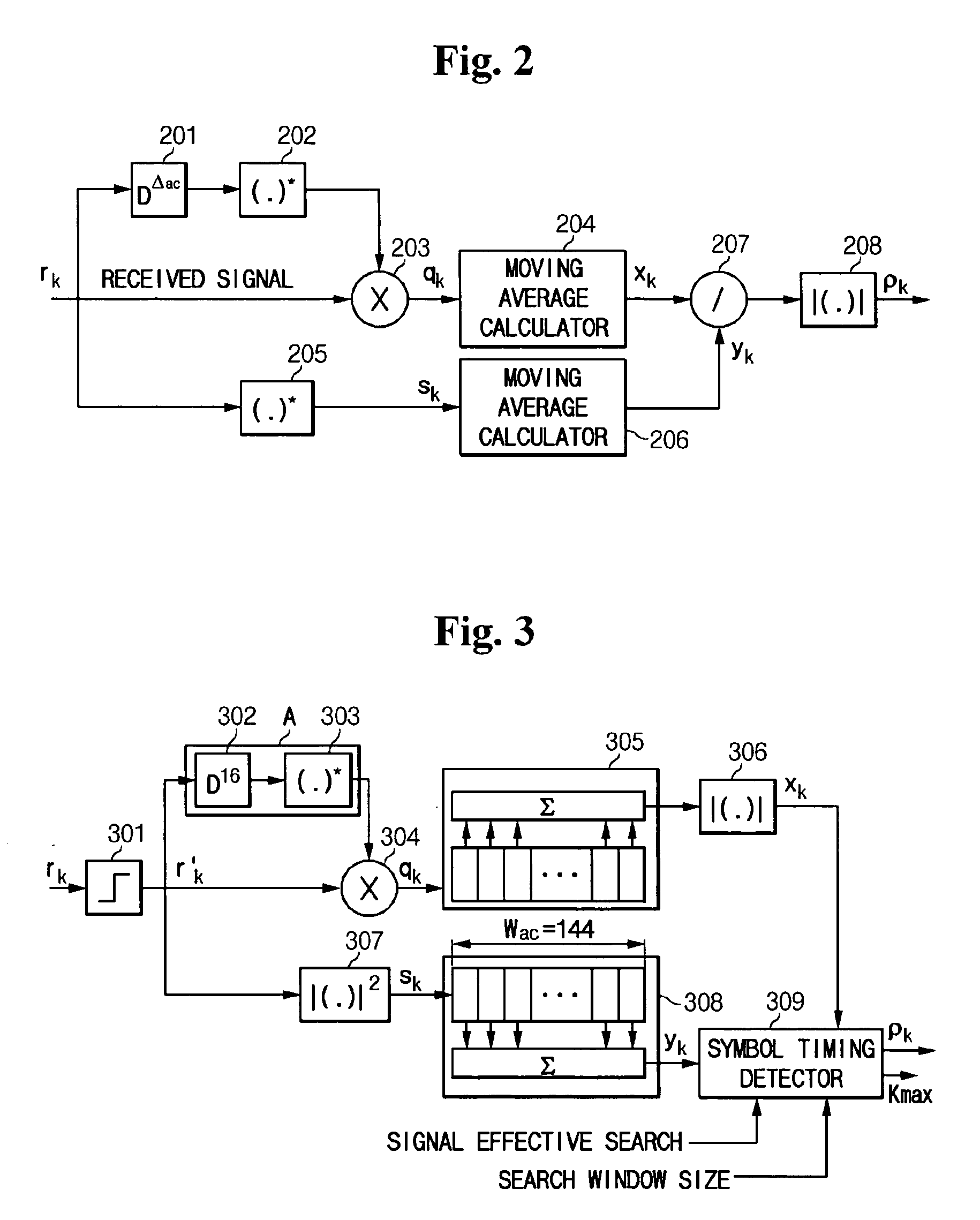
[0037]FIG. 3 is a block diagram of an apparatus for symbol timing detection according to the present invention.
[0038] The apparatus for symbol timing detection according to the first embodiment of the present invention comprises, as shown in FIG. 3, a mapper 301, an autocorrelation delay section 302, a complex conjugate processor 303, a multiplier 304, moving average calculators 305 and 308, an absolute value calculator 306, a squarer 307, and a symbol timing detector 309.
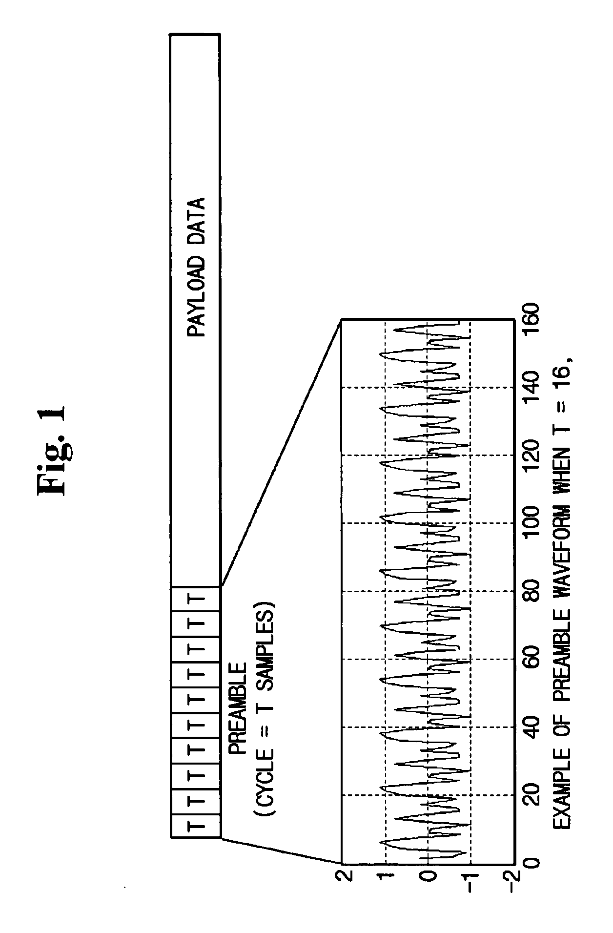
[0039] The mapper 301 maps the sample rk of a given preamble into a 1-bit sample rk. The reason why the sample of the preamble is mapped is that the output of the analog-to-digital converter using a sample of the interval involved in automatic gain control cannot be used as it is. The use of the sample of the preamble mapped into a 1-bit sample minimizes the effect of automatic gain control and has a benefit in the aspect of realization when a performance deterioration is not so significant relative to the case of...
second embodiment
[0057]FIG. 6 is a block diagram of an apparatus for symbol timing detection for a wireless communication system according to the present invention.
[0058] Referring to FIG. 6, the apparatus for symbol timing detection having the same structure of FIG. 3 is constructed in the second embodiment, according to which the moving average window size Wac is reduced to 48 so as to decrease required complexity per symbol period.
[0059] To unify the maximum of the theoretical autocorrelation, Δac must be 112 in consideration of the structure of a given preamble.
[0060] In the apparatus for symbol timing detection of the same structure of FIG. 3, the experimental values according to the second embodiment, in which the values Wac (=48) and Δac (=112) are varied, are given as follows.
[0061]FIG. 7 shows the output of a symbol timing detector in a white noise and delay spread channel environment in the apparatus of FIG. 6, and FIG. 8 shows the probability of causing an error in a white noise and de...
third embodiment
[0064]FIG. 9 is a block diagram of an apparatus for symbol timing detection for a wireless communication system according to the present invention.
[0065] Referring to FIG. 9, the apparatus for symbol timing detection according to the third embodiment, which is a modified structure of the apparatus for symbol timing detection according to the second embodiment as shown in FIG. 6, comprises an autocorrelation delay section 901, a mapper 902, a complex conjugate processor 903, multipliers 904 and 907, absolute value calculators 905 and 906, moving average calculators 908 and 909, an absolute value calculator 910, and a symbol timing detector 911.
[0066] The autocorrelation delay section 901, the mapper 902, and the complex conjugate calculator 903 have the same functions as described in the first embodiment and belong to an autocorrelation delay processor B for autocorrelation-delaying of the received signal, one-bit mapping, and then complex-conjugate processing.
[0067] The absolute v...
PUM
 Abstract
Description
Claims
Application Information
 - R&D
- Intellectual Property
- Life Sciences
- Materials
- Tech Scout
- Unparalleled Data Quality
- Higher Quality Content
- 60% Fewer Hallucinations
Browse by: Latest US Patents, China's latest patents, Technical Efficacy Thesaurus, Application Domain, Technology Topic, Popular Technical Reports.
© 2025 PatSnap. All rights reserved.Legal|Privacy policy|Modern Slavery Act Transparency Statement|Sitemap|About US| Contact US: help@patsnap.com


