Shakers and methods of testing

a shaker and shaker technology, applied in the direction of mechanical vibration separation, fluid tightness measurement, instruments, etc., can solve the problems of limiting the application and efficiency of use of shakers, limiting the utility of shakers, and normaly not being sealed devices

Active Publication Date: 2005-06-09
LUS & BUTTS
View PDF10 Cites 30 Cited by
  • Summary
  • Abstract
  • Description
  • Claims
  • Application Information

AI Technical Summary

Problems solved by technology

Such prior art shakers work well when properly used, though typically have certain characteristics which limit their application and the efficiency of their use.
By way of example, such shakers normally are not sealed devices to better facilitate cooling of the voice coil.
Because of this, they can accumulate dirt and moisture, limiting their utility when regularly used in an uncontrolled environment or in testing over a temperature range particularly in low temperatures.
In particular, conventional shaker armature suspension systems limit the size of the test specimen and / or increase the complexity of the test fixturing required for larger or heavier test specimens.
Although conventional shaker suspensions are made as stiff as possible in the lateral directions, their lateral stiffness is limited by the need to reduce the axial (normal vibration axis) armature suspension stiffness so as not to affect the axial vibration force requirements and to provide adequate amplitudes of vibration for low frequency testing.
During normal axial vibration test excitation, off-center loading or unsymmetrical stiffness components of the test specimen necessarily result in some lateral or rotational vibration motion.
Due to the extremely close tolerances involved with the voice coil, these lateral vibration components can result in internal shaker mechanical component contact and subsequent damage to the shaker.
This situation often results in severe limitations on the size or weight of the test specimen that can be tested on a given shaker.

Method used


Image

  • Shakers and methods of testing
  • Shakers and methods of testing
  • Shakers and methods of testing

Examples


Embodiment Construction

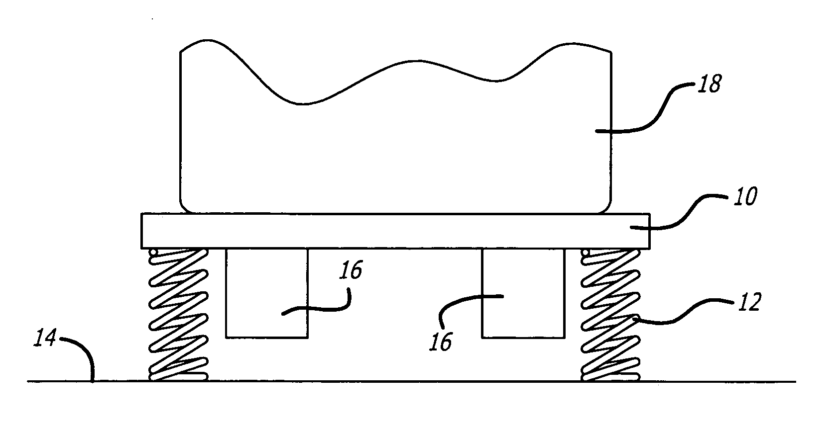
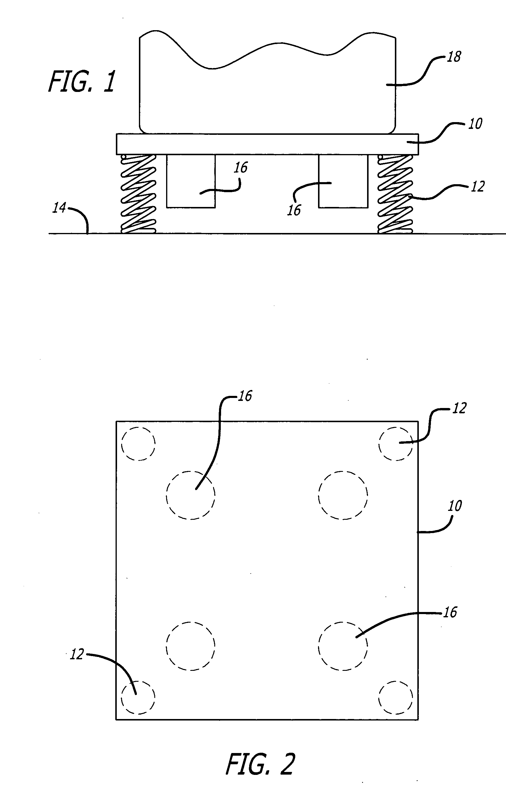
[0017] The present invention comprises a sealed, liquid-cooled shaker not having a conventional shaker table to which an article to be tested is placed, but rather having a housing to which the vibratory forces are coupled. Thus the housing of one or more such shakers, each of which may be substantially smaller than the article to be tested, may be coupled directly to the article to be tested, or alternatively may be coupled singularly or in plurality to a suitable table or platform to which the article to be tested is connected. By way of example, referring to FIG. 1, a table 10 supported by coil springs 12 on a suitable support surface 14 is schematically illustrated. Here a plurality of shakers 16, four in this specific embodiment (see FIG. 2 also), are used to impart vibratory forces to the table 10 and thus to the object 18 being tested. Since each shaker is, capable of generating very substantial vibratory forces for its size and frequently large objects are only tested at rel...


PUM


Abstract

Shakers and methods of testing suitable for various applications, including those presenting adverse test environments. The shakers have a permanent magnet assembly mounted in a sealed housing for vibration along a shaker axis. The permanent magnet assembly is double ended, and includes at least one shorting ring to hold down the inductance of the driving coils at higher frequencies. Fluid cooling (or heating) of both the shaker housing and the permanent magnet assembly allows placement of the shakers inside a temperature test chamber. The shakers may be coupled directly to the article to be tested, or coupled singularly or in a plurality to a test table to which an article to be tested is coupled. Various embodiments and methods of testing are disclosed.

Description

BACKGROUND OF THE INVENTION [0001] 1. Field of the Invention [0002] The present invention relates to the field of vibration test equipment and vibration testing. [0003] 2. Prior Art [0004] Vibration testing and equipment for such testing is well known in the prior art. The purpose of such testing varies from making sure that a product will operate properly in whatever vibration environment it will experience in normal use to simply assuring that the product will not be damaged by vibration levels that may be encountered during transportation of the product to its final destination. Thus in some cases the product being tested, such as a mechanical, electromechanical or electronic product, may be tested in operation, whereas in other cases, such as by way of example testing of home appliances, the product being tested when not operated, and in still other cases of course, a mechanical assembly may have no moving parts but still must meet minimum vibration capability requirements for s...

Claims


Application Information

Patent Timeline
Patent Type & Authority Applications(United States)
IPC IPC(8): G01M7/04
CPCG01M7/04B06B1/04G01M7/02H02K33/18
Inventor BUTTS, GARY C.
Owner LUS & BUTTS
Why Eureka
Try Eureka