Electrical appliance having a wire winding device

Inactive Publication Date: 2005-06-09
TSANN KUEN ENTERPRISE
View PDF33 Cites 12 Cited by
  • Summary
  • Abstract
  • Description
  • Claims
  • Application Information

AI Technical Summary

Benefits of technology

[0007] Therefore, the main object of the present invention is to provide

Problems solved by technology

This can damage the e

Method used


Image

  • Electrical appliance having a wire winding device
  • Electrical appliance having a wire winding device
  • Electrical appliance having a wire winding device

Examples


Example

[0021] Before the present invention is described in greater detail, it should be noted that like elements are denoted by the same reference numerals throughout the disclosure.

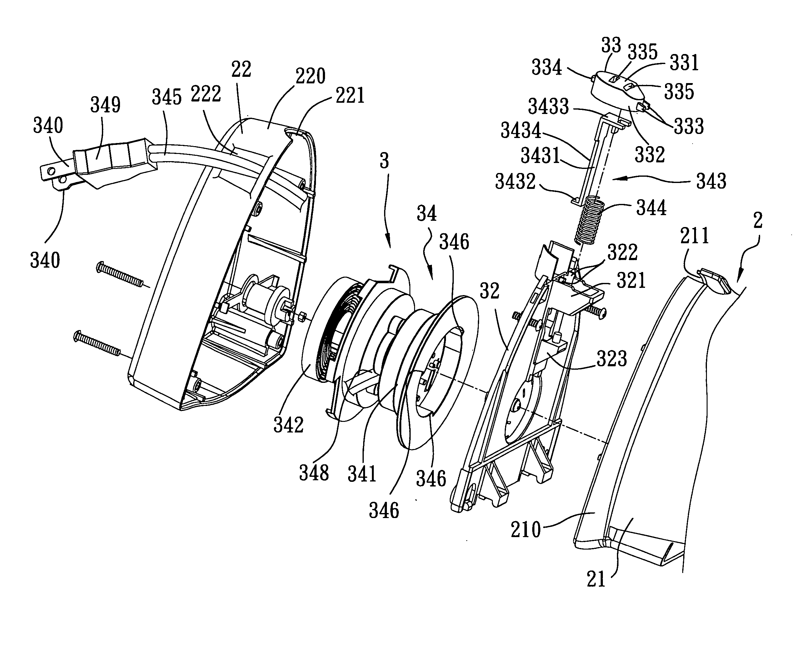
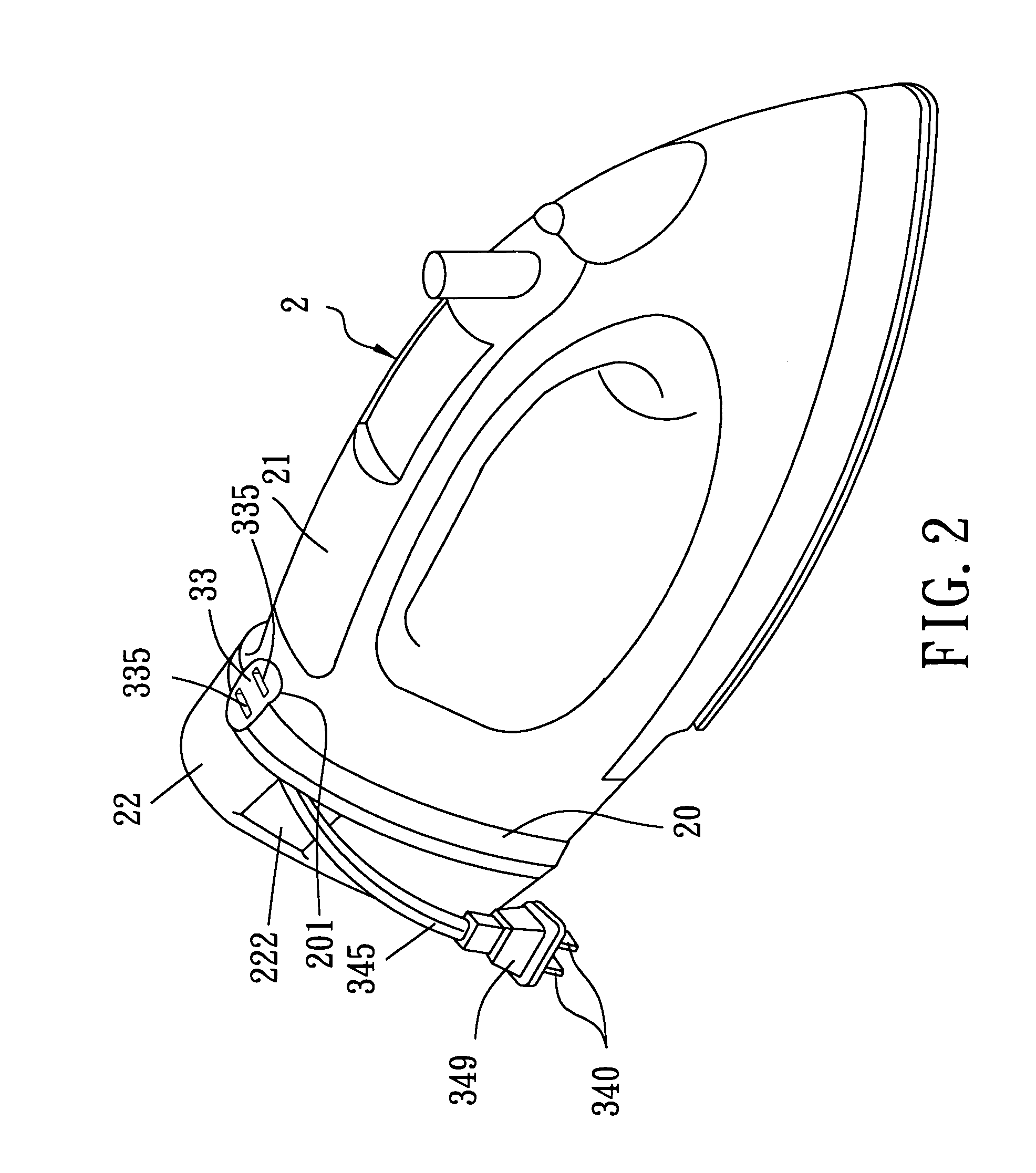
[0022] Referring to FIGS. 2 to 4, the first preferred embodiment of an electrical appliance according to the present invention is shown to comprise a main housing 2 enclosing an electric unit (not shown), and a wire winding device 3. In this embodiment, the electrical appliance is exemplified as a press iron. However, other electrical appliances, such as a vacuum cleaner, a coffee maker, cooking appliance, etc., are also applicable in the present invention.

[0023] The main housing 2 has a front housing 21 with a front wall 210, a rear housing 22 with a rear wall 220 that cooperates with the front wall 210 to form an outer wall 20 (see FIG. 2), and a partition plate 32. The front wall 210 has a notch portion 211 (see FIG. 3) formed on a top periphery thereof and extending frontwardly. The rear wall 220 has a no...


PUM


Abstract

An electrical appliance includes a housing, an electric unit mounted within the housing, a winding unit mounted within the housing and including a reel member, an electrical wire connected electrically to the electric unit and wound around the reel member, and a latch unit engaging releasably the reel member to prevent the reel member from rotation in a winding direction of the reel member. The electrical wire has one end provided with a plug portion. The housing has at least one insert hole proximate to the latch unit for extension of the plug portion there through so as to press and disengage the latch unit from the reel member, thereby permitting the winding unit to wind the electrical wire.

Description

BACKGROUND OF THE INVENTION [0001] 1. Field of the Invention [0002] The invention relates to an electrical appliance, more particularly to an electrical appliance having a wire winding device, and to a method of winding an electrical wire of the electrical appliance. [0003] 2. Description of the Related Art [0004] Referring to FIG. 1, a conventional electrical appliance 1 with a wire winding device includes a housing 11, an electrical wire 12 having a plug portion 121 at one end, a winding unit (not shown) disposed within the housing 11 for winding and unwinding the electrical wire 12, and a control knob 14 disposed on the housing 11 for controlling rotation of the winding unit. The housing 11 is formed with a through hole 111 for extension of the electrical wire 12 there through. The through hole 111 has a diameter smaller than that of the plug portion 121 so that the plug portion 121 protrudes out of the through hole 111. [0005] To use the conventional electrical appliance 1, a su...

Claims


Application Information

Patent Timeline
IPC IPC(8): D06F75/28H02G11/02
CPCD06F75/28B65H75/4431B65H75/42H02G11/02
Inventor CHI, SHANG-FEI
Owner TSANN KUEN ENTERPRISE
Why Eureka
Try Eureka