
Power connector with improved contact structure

a technology of contact structure and power connector, which is applied in the direction of coupling device connection, coupling protective earth/shielding arrangement, electric discharge lamps, etc., can solve the problems of accidental shorting between multiple contacts and unsure electrical contacts

Inactive Publication Date: 2005-06-09
HON HAI PRECISION IND CO LTD
View PDF8 Cites 73 Cited by
  • Summary
  • Abstract
  • Description
  • Claims
  • Application Information

AI Technical Summary

Benefits of technology

[0007] In order to achieve the above-mentioned object, a power connector in accordance with the present invention includes an insulating housing, a plurality of contacts received in the insulative housing and a conductive shield comprising a first shielding shell and a second shielding shell. The insulating housing has a base, a tongue extending horizontally from the base and comprising a upper mating face and a lower mating face parallel to the upper mating face, and a pair of mounting portions adjacent to the base. A plurality of receiving passages are defined through the base toward the tongue for receiving the contacts. A plurality of receiving slots extend from the upper mating face to the lower mating face and communicate with corresponding receiving passages. Each of the contacts has a contact portion received in corresponding receiving slot and the contact portion comprises a first and a second contact surfaces respectively exposed to the upper mating face and the lower mating face. The contacts are surrounded by the insulative housing and distributed along the receiving passages and slots, with plastic of the housing separating one contact from the other to preclude accidental shorting as between multiple contacts. As the power connector mates with a complementary connector, the first and the second contact surfaces of the contacts enlarge contact surface area, thereby to insure electrical connection between connectors.

Problems solved by technology

However, the insulating housing of the plug contacts is configured in an L-shape and the plug contacts are mainly exposed to the air and the separated space between the contacts is small such that if there is metal thing dropt into the plug, accidental shorting will happen between multiple contacts also.
In addition, the electrical contact is unsure between contacts of the power connector and mating contacts of a complementary connector for small contact surfaces of the contacts.

Method used


Image

  • Power connector with improved contact structure
  • Power connector with improved contact structure
  • Power connector with improved contact structure

Examples


Embodiment Construction

[0017] Reference will now be made to the drawing figures to describe the present invention in detail.

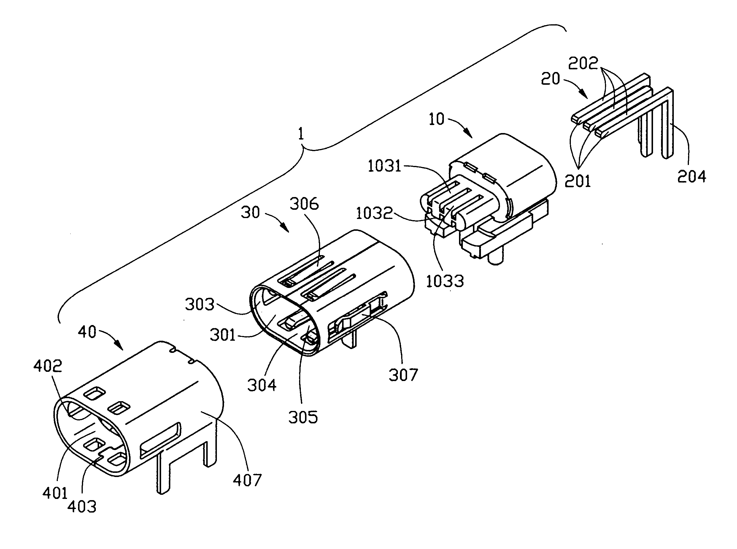
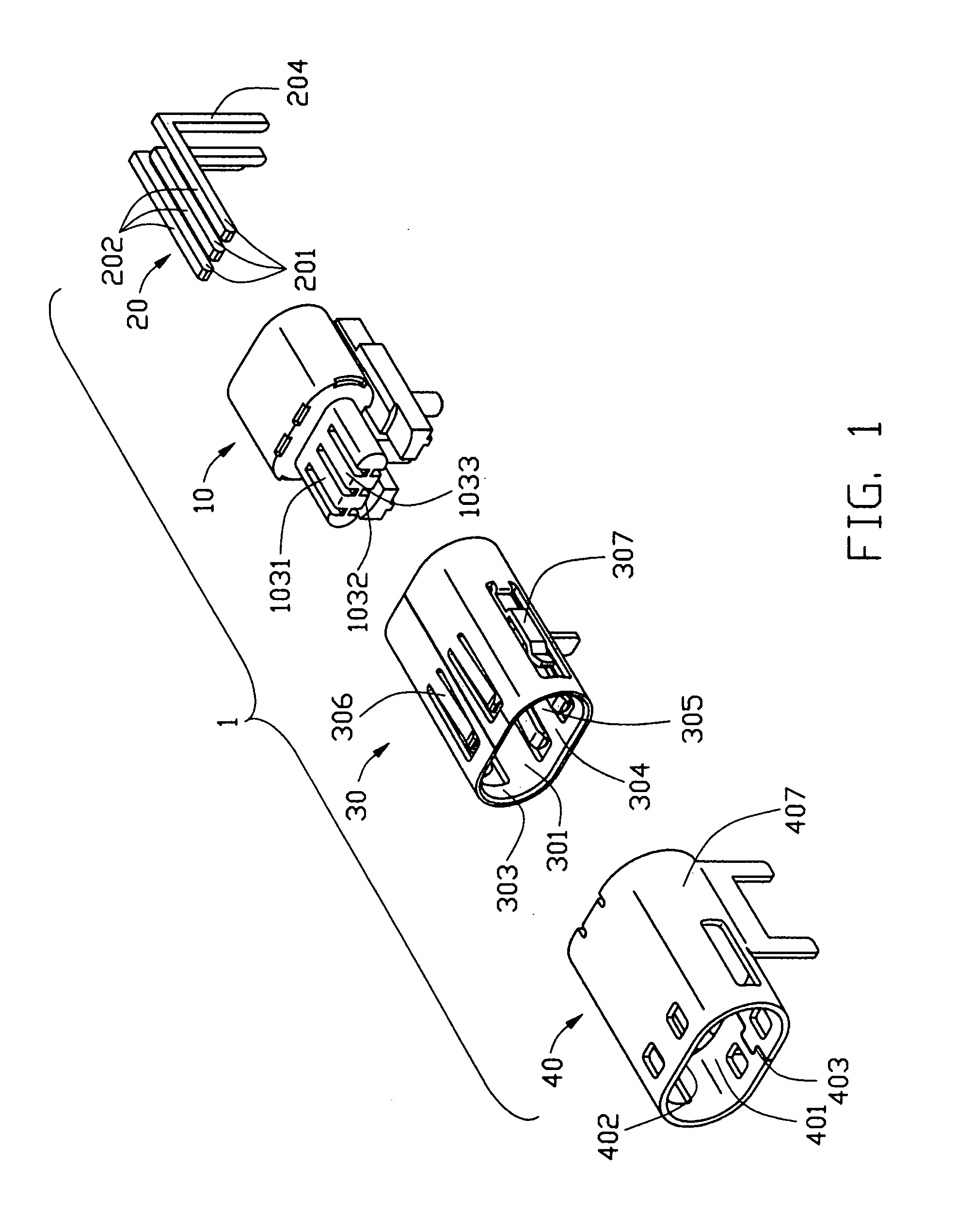
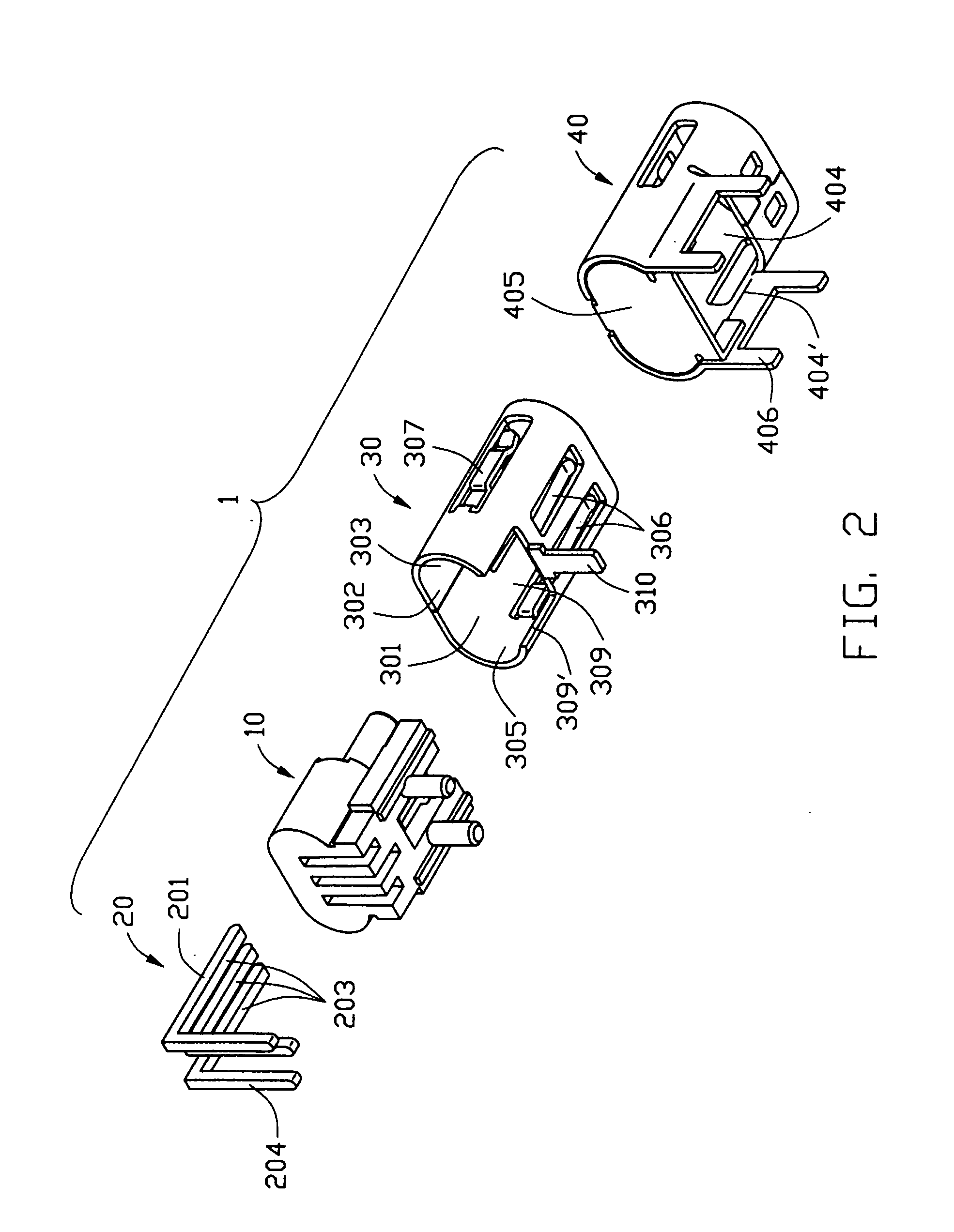
[0018] Referring to FIGS. 1 and 2, a power connector 1 in accordance with the present invention includes an insulating housing 10, a plurality of contacts 20 received in the insulative housing 10 and a conductive shield comprising a first shielding shell 30 and a second shielding shell 40.

[0019] With reference to FIGS. 3-5, the insulating housing 10 comprises a base 101, a tongue 103 extending forwardly from the base 101, and two mounting portions 107 below the base 101. The base 101 is about columned-shaped and comprises a front face 102 and an opposite rear face 114. The tongue 103 has an upper mating face 1031 and an opposite lower face 1032. A plurality of receiving slots 104 extend from the upper mating face 1031 to the lower mating face 1032. Each receiving slot 104 defines a stop block 106 thereof exposed to a front surface 1033 of the tongue 103. A plurality of receiving pa...


PUM


Abstract

A power connector (1) includes an insulating housing (10), a number of contacts (20) received in the insulative housing, a first and a second shielding shells (30,40). The insulating housing has a base (101), and a tongue (103) extending horizontally from the base and including an upper mating face (1031) and a lower mating face (1032) parallel to the upper mating face. A number of receiving passages (105) are defined through the base toward the tongue. A plurality of receiving slots (104) extend from the upper mating face to the lower mating face to communicate with corresponding receiving passages. Each contact has a contact portion (201) received in corresponding receiving slot. The contact portion has a first and a second contact surfaces (202, 203) respectively exposed in the upper and the lower mating face.

Description

BACKGROUND OF THE INVENTION [0001] 1. Field of the Invention [0002] The present invention generally relates to a power connector, and particularly to a power connector having improved contact structure. [0003] 2. Description of Prior Arts [0004] With the development of integrated circuits, the trend toward high density of components used in electronic packaging, such as those used for computers and the like, is continuing. Thus, there are the needs for power connectors to carry the power required by densely spaced logic and memory components and to insure the electrical connection of the contacts for avoiding the risk of shorting. In response to the need to carry different levels of voltage current, power connectors with multi-contacts capabilities are fabricated. U.S. Pat. No. 5,158,471 disclosed such a power connector. The power connector for interconnecting power between printed circuit boards includes plug and receptacle contacts, which are arranged adjacent to signal connector ...

Claims


Application Information

Patent Timeline
IPC IPC(8): H01R12/16
CPCH01R12/7088H01R23/6873H01R13/658
Inventor CHEN, WEI-XINGZHUANG, QUANWANG, NINGCHEN, ZHI-QIANGXUE, YA-LEIPENG, BIN
Owner HON HAI PRECISION IND CO LTD
Features
  • Generate Ideas
  • Intellectual Property
  • Life Sciences
  • Materials
  • Tech Scout
  • Unparalleled Data Quality
  • Higher Quality Content
  • 60% Fewer Hallucinations
Learn More