
Locking structure for combing a hook and a hanging ring

Inactive Publication Date: 2005-06-16
HONG STEVEN
View PDF10 Cites 16 Cited by
  • Summary
  • Abstract
  • Description
  • Claims
  • Application Information

AI Technical Summary

Benefits of technology

[0005] The locking section of the hook member is inserted through the ring coupler of the hanging ring and connects the screw nut. The screw nut is twisted and moved along the locking section to align two opposite retaining slots with the through hole of the locking section. The spring lock pin is inserted through the through hole and those two opposite retaining slots so as to lock the hook member and the hanging ring together. Thereby, the self-gravity of the hook member can pull the screw nut downward with respect to the ring coupler of the hanging ring so that the spring lock pin is pressed against an upper horizontal face of the screw nut and thus secured, without a riveting mechanism necessary in the conventional locking structure.

Problems solved by technology

The conventional locking structure for combing a hook and a hanging ring is disadvantageous in that the space encircled by the hanging ring 2 and the associated ring coupler 21 is so limited so that the riveting job therebetween is difficult.

Method used


Image

  • Locking structure for combing a hook and a hanging ring
  • Locking structure for combing a hook and a hanging ring
  • Locking structure for combing a hook and a hanging ring

Examples


Embodiment Construction

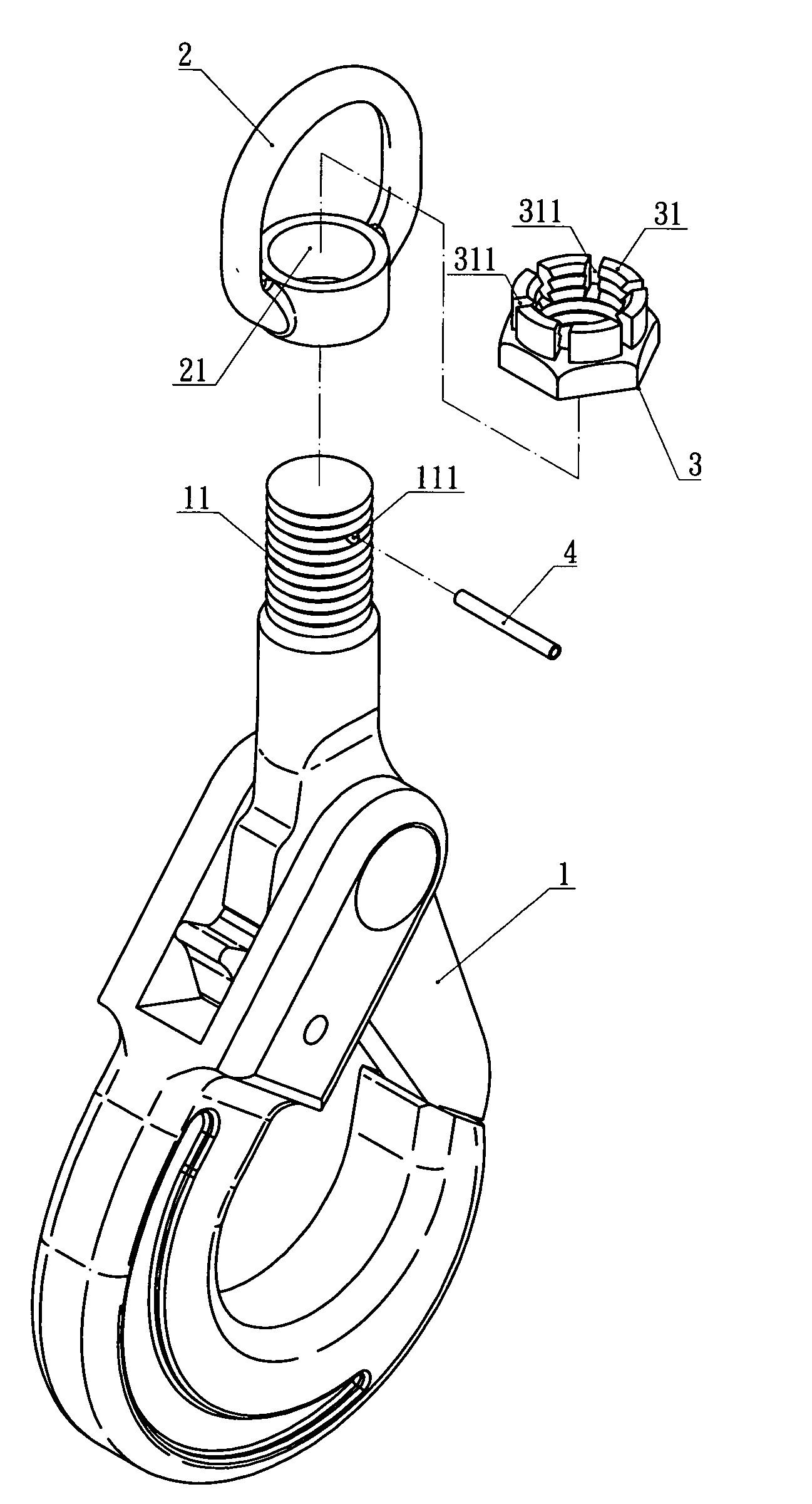
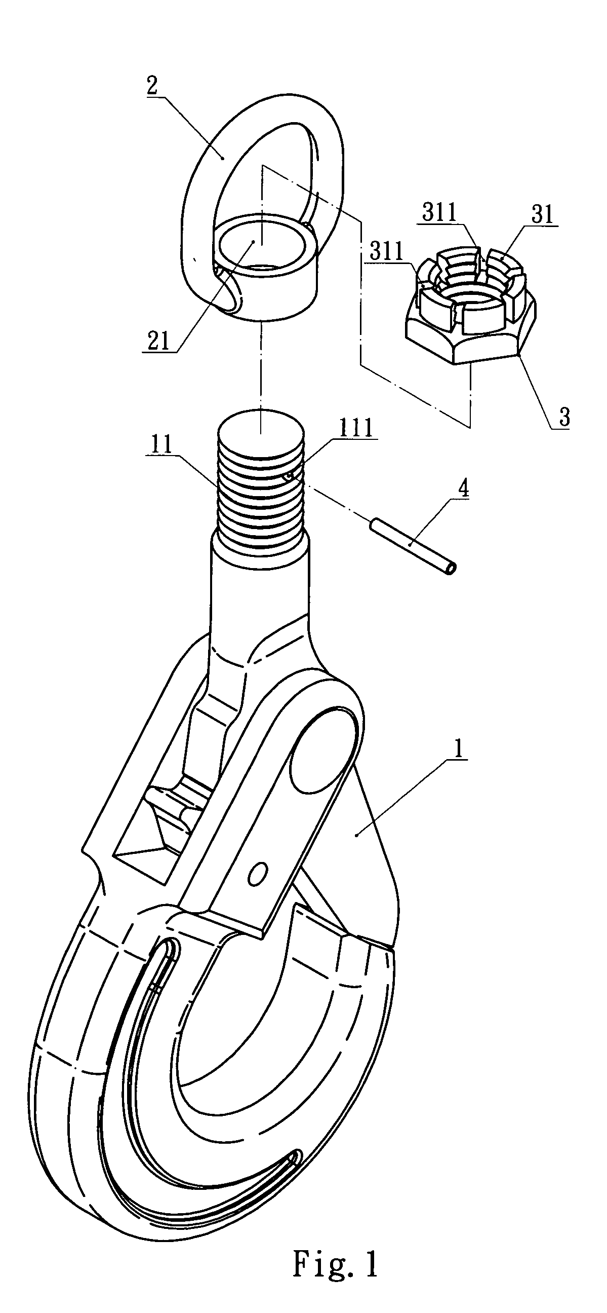
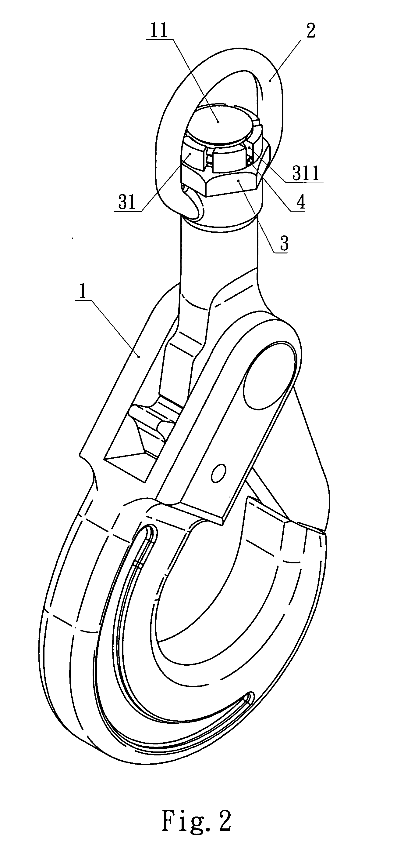
[0010] Referring to FIGS. 1 and 2, a locking structure for combing a hook and a hanging ring according to the present invention comprises a hook member 1 and a hanging ring 2 attached with the hook member 1. A hook member 1 includes a cylindrical section extending in the upward direction. The upper portion of the section, being provided with a helical screw groove, defines a locking section 11. The locking section 11 further includes a through hole 111 that goes transversely across the locking section 11.

[0011] The hanging ring 2 further includes a ring coupler 21 for being put around the locking section 11 of the hook member 1 in a way that the locking section 11 extends through the ring coupler 21 of the hanging ring 2. After the hanging ring 2 is mounted onto the locking section 11 of the hook member 1, a screw nut 3 is applied to the top portion of the locking section 11. The screw nut 3 has a plurality of radially distributed blocks 31, forming a circle designed to be smaller ...


PUM


Abstract

A locking structure for combing a hook and a hanging ring comprises a hook member, a hanging ring, a screw nut and a spring lock pin. The screw nut having a plurality of radially distributed blocks formed on an upper end thereof. And the spaces between adjacent blocks define a plurality of radially distributed retaining slots. The locking section of the hook member is inserted through the base of the hanging ring and connects the screw nut. The spring lock pin is inserted through the through hole and two opposite retaining slots so as to lock the hook member and the hanging ring together. Thereby, the self-gravity of the hook member can pull the screw nut downward so that the spring lock pin is pressed against the screw nut and thus secured, without the riveting mechanism necessary in conventional locking structures.

Description

FIELD OF INVENTION [0001] The present invention relates to locking structures for combing a hook and a hanging ring, more particularly to a locking structure for combing a hook and a hanging ring in which a lock pin is retained within a screw nut mounted on the hook and is secured by the self gravity of the hook. DESCRIPTION OF THE PRIOR ART [0002] Referring to FIG. 4, a locking structure for combing a hook and a hanging ring of the prior art comprises a hook member 1 and a hanging ring 2; the hanging ring 2 is mounted on the top end of the hook member 1. A locking section 11A with helical screw groove extends from the top of the hook member 1. A fixing tab 112 is formed at the top end of the locking section 11A. The hanging ring includes a ring coupler 21 that can be coupled with the locking section 11A and gets secured thereon by a screw nut 3A mounted above the ring coupler 21. A riveting machine presses the fixing tab 112 on a blocking plate 311 so as to lock the hanging ring 2 ...

Claims


Application Information

Patent Timeline
IPC IPC(8): F16B39/04F16B45/02
CPCF16B39/04Y10T24/4755F16B45/02F16B45/034
Inventor HONG, STEVEN
Owner HONG STEVEN
Features
  • Generate Ideas
  • Intellectual Property
  • Life Sciences
  • Materials
  • Tech Scout
  • Unparalleled Data Quality
  • Higher Quality Content
  • 60% Fewer Hallucinations
Learn More