Cryogenic cooling apparatus

a technology of cryogenic cooling and apparatus, which is applied in the direction of domestic cooling apparatus, lighting and heating apparatus, container discharge methods, etc., can solve the problems of cyclic vibration which is transmitted to the entire cryostat and the object, providing further vibration to the object to be cooled, and affecting the entire cryostat. , to achieve the effect of preventing vibration transmission

Inactive Publication Date: 2005-06-16
SUMITOMO HEAVY IND LTD +1
View PDF7 Cites 39 Cited by
  • Summary
  • Abstract
  • Description
  • Claims
  • Application Information

AI Technical Summary

Benefits of technology

[0011] The present invention was made in order to overcome the drawbacks of the aforementioned conventional techniques, and aims to prevent transmission of vibration which occurs due to the refrigerator to the entire cryostat and the object to be cooled.

Problems solved by technology

Thus, mechanical vibration from that compressor is transmitted to a cold head that is a cooling portion attached to the cryostat through an interconnecting tube for connecting the compressor and the cold head, thereby affecting the entire cryostat.
Moreover, in a case of a refrigerator including a piston (also referred to as a displacer) within the cold head, such as a GM refrigerator or a Stirling refrigerator, reciprocating motion of the piston involved with compression and expansion causes cyclic vibration which is transmitted to the entire cryostat and the object to be cooled.
Furthermore, since a cylinder of the refrigerator typically has a cylindrical thin structure, pressure oscillation between a higher pressure and a lower pressure in the cold head involved with compression / expansion causes elastic expansion and contraction of the cylinder, providing further vibration to the object to be cooled.
Therefore, vibration transmitted through the supporting bars cannot be blocked.
However, since the inside of the cryostat is kept vacuum, the bellows contracts and loses its flexibility.
Therefore, the expected effect of attenuating vibration cannot be achieved.
Therefore, vibration cannot be blocked sufficiently.

Method used


Image

  • Cryogenic cooling apparatus
  • Cryogenic cooling apparatus
  • Cryogenic cooling apparatus

Examples


first embodiment

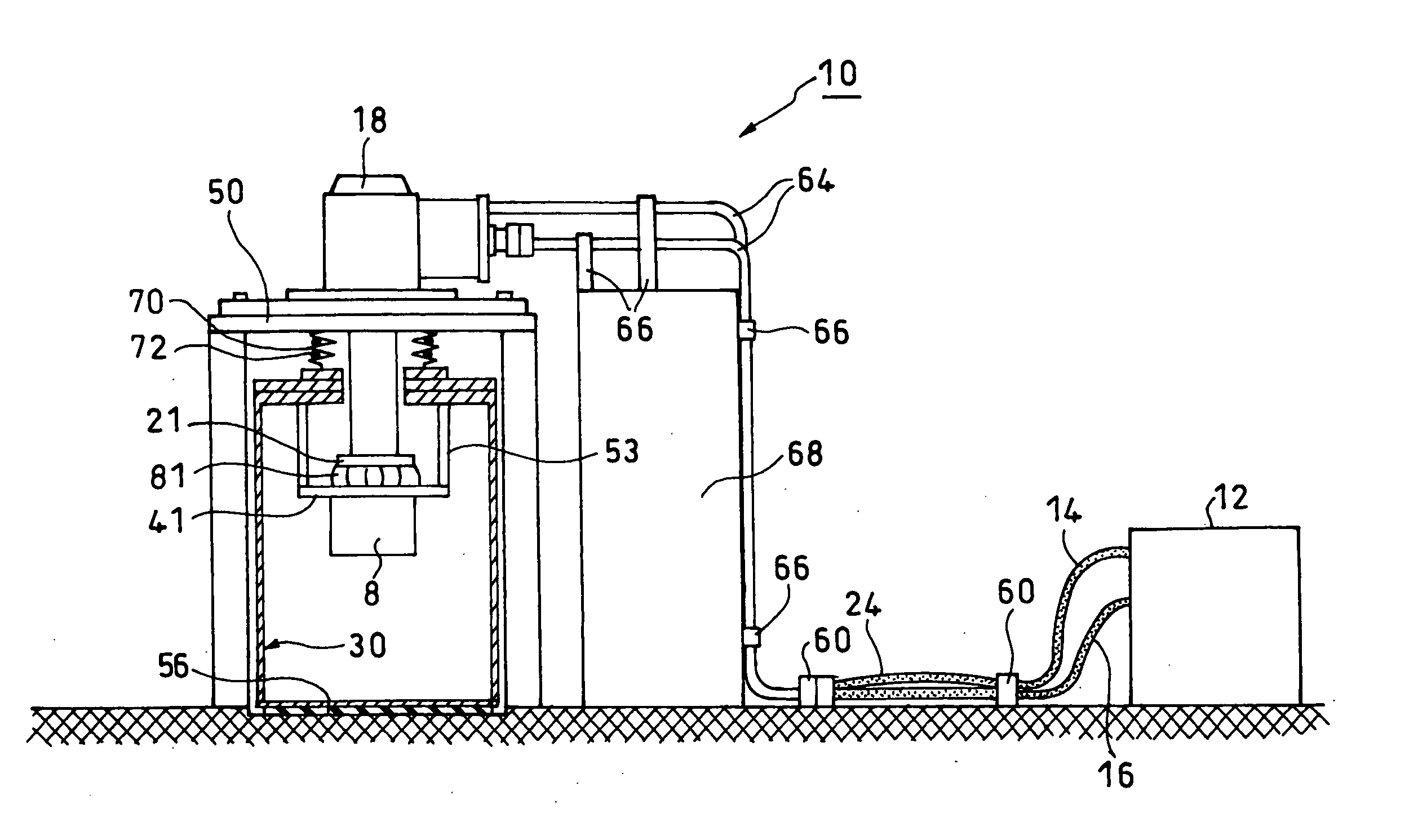
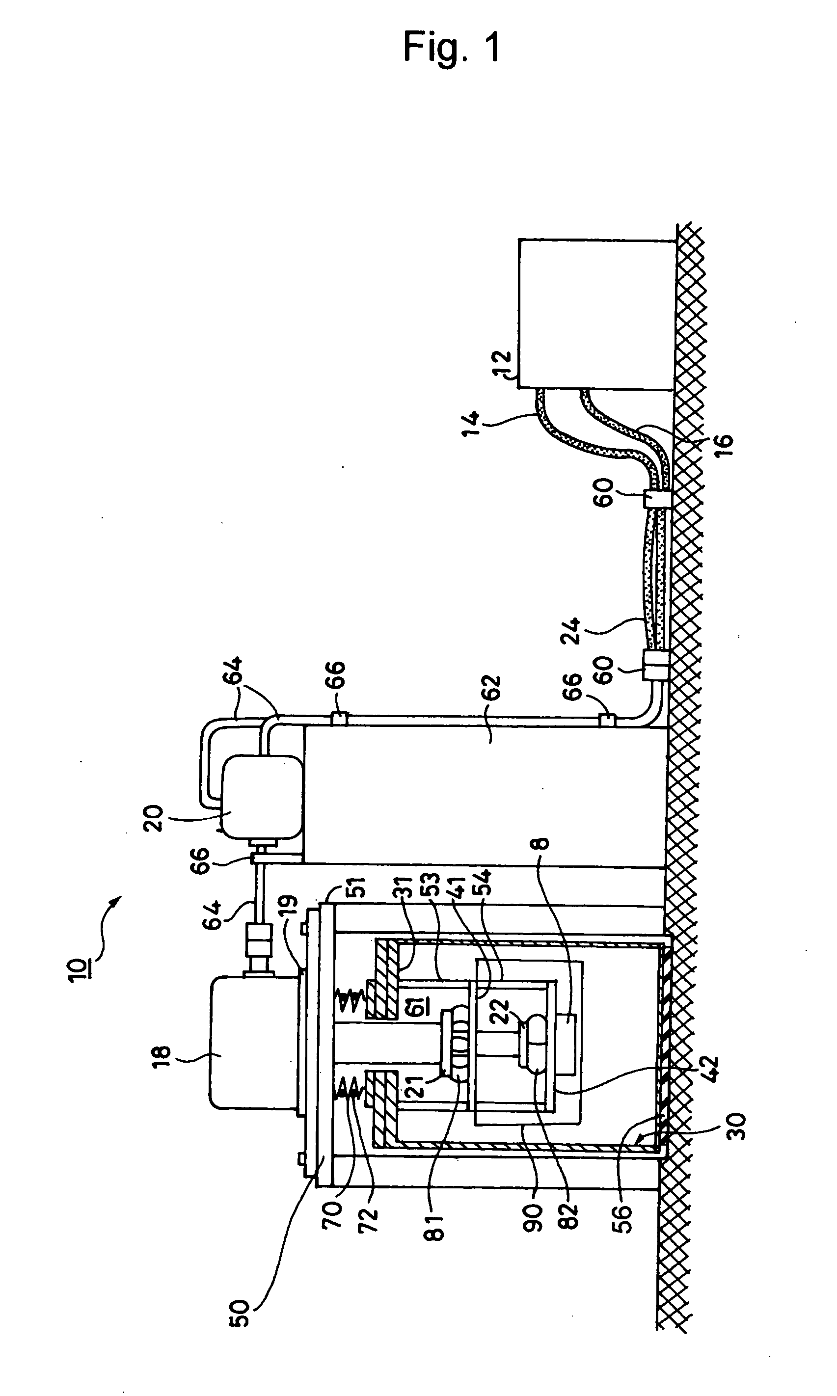
[0028] In a first embodiment as shown in FIG. 1, the present invention is applied to a cryogenic cooling apparatus using a two-stage GM pulse tube refrigerator, or a two-stage GM refrigerator (hereinafter, simply referred to as refrigerator) In this refrigerator 10, a valve unit 20 for switching a pressure of gas supplied from a compressor 12 of the refrigerator 10 to a cold head 18 via a high-pressure gas line 14 and a low-pressure gas line 16 can be separated from the cold head 18. The cold head 18 of the refrigerator 10 is not secured directly to a cryostat 30 but is secured to a support stage 50 that is provided separately from the cryostat 30. Thus, the support stage 50 supports the load of the cold head 18. Moreover, a second low-vibration stage 42, to which an object to be cooled 8 is secured and which supports the load of the object 8, is secured to the cryostat 30 (its top flange 31 in the example shown in FIG. 1) via supporting bars 53 and 54. As shown in FIG. 1, the cold ...
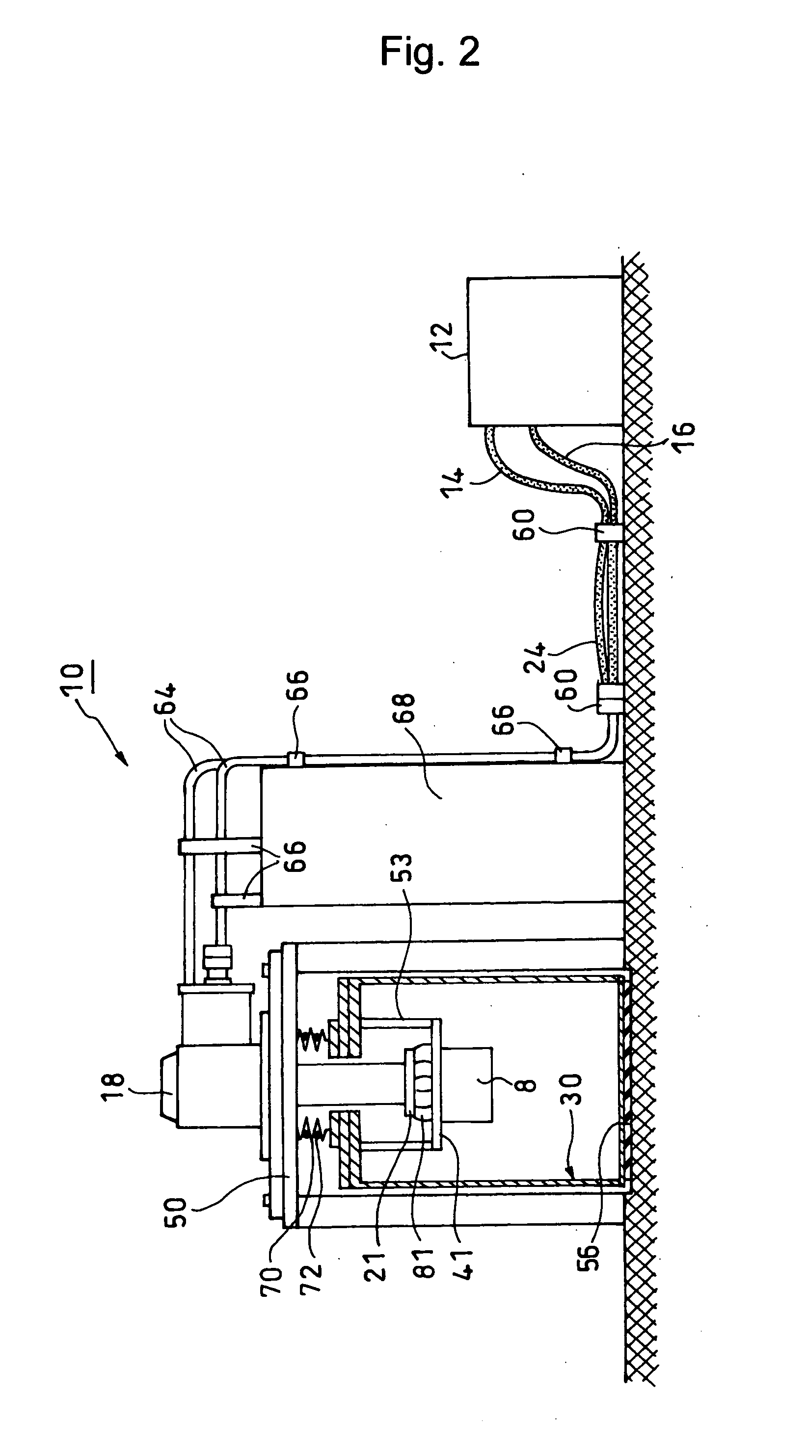
second embodiment

[0053] Except for the above, the present embodiment is the same as the Thus, the further description of the present embodiment is omitted.

[0054] In the above embodiments, the GM pulse tube refrigerator is a two-stage type, while the other refrigerator is a single stage type. However, a combination of the number of stages and the type of the refrigerator is not limited to the above. Various combinations can be used.

[0055] The present invention can also be applied to a superconducting apparatus, a device cooling apparatus, a detector cooling apparatus, a sample cooling apparatus, a cryopump apparatus, a measurement and analysis apparatus, an NMR apparatus and the like, which require lower vibration.


PUM


Abstract

A cold head of a refrigerator is secured to a support stage provided separately from a cryostat so that the support stage supports the load of the cold head. On the other hand, a low-vibration stage for supporting a load of an object to be cooled is secured to a top flange of the cryostat. Thus, vibration that occurs due to the refrigerator is prevented from being transmitted to the entire cryostat and the object to be cooled.

Description

BACKGROUND OF THE INVENTION [0001] 1. Field of the Invention [0002] The present invention relates to a cryogenic cooling apparatus including a cryostat cooled by a refrigerator. More particularly, the present invention relates to a cryogenic cooling apparatus which can prevent vibration generated by the refrigerator from being transmitted to the entire cryostat or an object to be cooled and is suitable for a Gifford-McMahon type (GM) pulse tube refrigerator or a Gifford-McMahon cycle refrigerator (GM refrigerator) in which a valve unit can be separated from a cold head. [0003] 2. Description of the Related Art [0004] In a cryogenic cooling apparatus including a cryostat cooled by using a refrigerator, several kinds of vibration typically caused by the refrigerator occurs and is transmitted to the entire cryostat and an object to be cooled. More specifically, a compressor serving as a source of pressure oscillation is mechanical type. Thus, mechanical vibration from that compressor i...

Claims


Application Information

Patent Timeline
Patent Type & Authority Applications(United States)
IPC IPC(8): F25B9/00F17C13/00F25B9/14
CPCF17C2203/0391F25D19/006F17C2205/0126F17C2223/0161F17C2223/033F17C2227/0353F17C2227/0369F17C2260/01F17C2270/0527F25B9/10F25B9/14F25B9/145F25B2309/14181F25B2500/13F17C2205/0107
Inventor LI, RUIIKUSHIMA, YUKISUZUKI, TOSHIKAZUTOMARU, TAKAYUKISHINTOMI, TAKAKAZUHARUYAMA, TOMIYOSHI
Owner SUMITOMO HEAVY IND LTD
Why Eureka
Try Eureka