
Hydraulic transaxle and vehicle comprising it

a transaxle and hydraulic technology, applied in the direction of non-deflectable wheel steering, mechanical devices, transportation and packaging, etc., can solve the problems of disadvantageous traveling capacity of vehicles, disadvantageous minimization of conventional vehicles, and non-drively connected steering wheels to prime movers

Inactive Publication Date: 2005-06-16
KANZAKI KOKYUKOKI MFG
View PDF17 Cites 11 Cited by
  • Summary
  • Abstract
  • Description
  • Claims
  • Application Information

AI Technical Summary

Benefits of technology

[0011] A first object of the present invention is to provide a compact and convenient hydraulic transaxle incorporating a hydraulic motor for driving a steerable wheel.
[0012] To achieve the object, according to a first aspect of the present invention, a steerable hydraulic transaxle comprises: a kingpin relatively rotatably supported by a vehicle chassis; a housing fixed to the kingpin; a single axle disposed in the housing; a single wheel fixed onto the single axle out of the housing; and a hydraulic motor disposed in the housing so as to drive the single axle. As a result, the housing supporting the single wheel is supported by the vehicle chassis so as to be rotatable around the center axis of the kingpin. Such a compact transaxle is advantageous in ensure a free space in a small size vehicle.
[0013] Preferably, the single axle is coaxially disposed in the hydraulic motor, thereby facilitating minimization of the steerable hydraulic transaxle.

Problems solved by technology

However, the steerable wheels are not drivingly connected to a prime mover.
Such a vehicle is disadvantageous in traveling capacity on a bad road and climbing capacity.
This conventional vehicle is disadvantageous in minimization because the hydraulic motors and the respective deceleration gear train housings are mounted upright on the vehicle chassis.
The vehicle is also disadvantageous in cost because of the two hydraulic pump.
Further, when the vehicle travels in the four-wheel drive mode, the front and rear hydraulic motors on each of left and right sides of the vehicle are fluidly connected in parallel to the common left or right hydraulic pump, so that the amount of hydraulic fluid supplied to each of the hydraulic motors is restricted.
Therefore, the vehicle is disadvantageous in efficiency of acceleration, i.e., high-speed traveling.
Further, the large transaxle including the transaxle housing and the left and right wheel support units is not handy, and is disadvantageous in ensuring a free space in a small size vehicle.

Method used


Image

  • Hydraulic transaxle and vehicle comprising it
  • Hydraulic transaxle and vehicle comprising it
  • Hydraulic transaxle and vehicle comprising it

Examples


Embodiment Construction

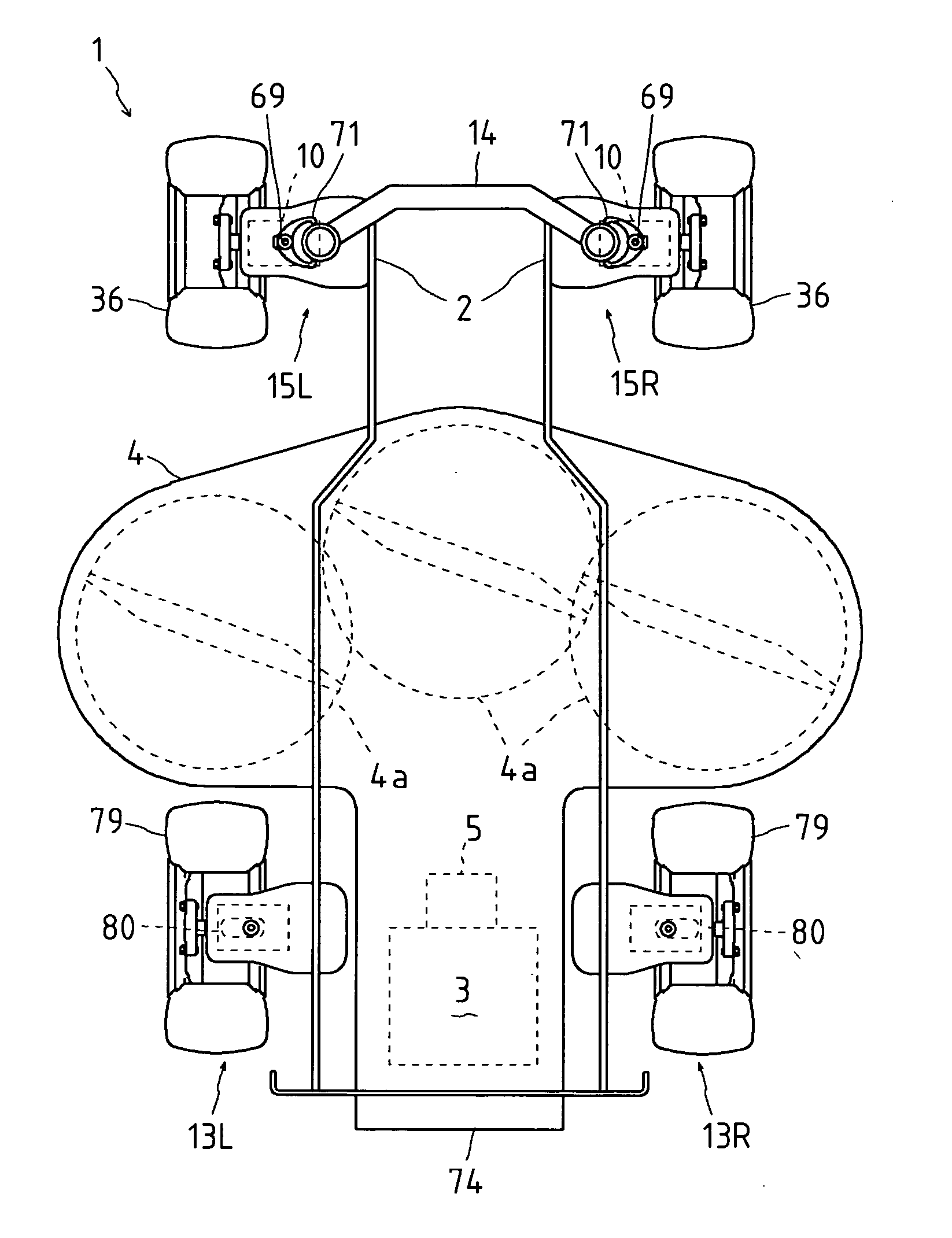
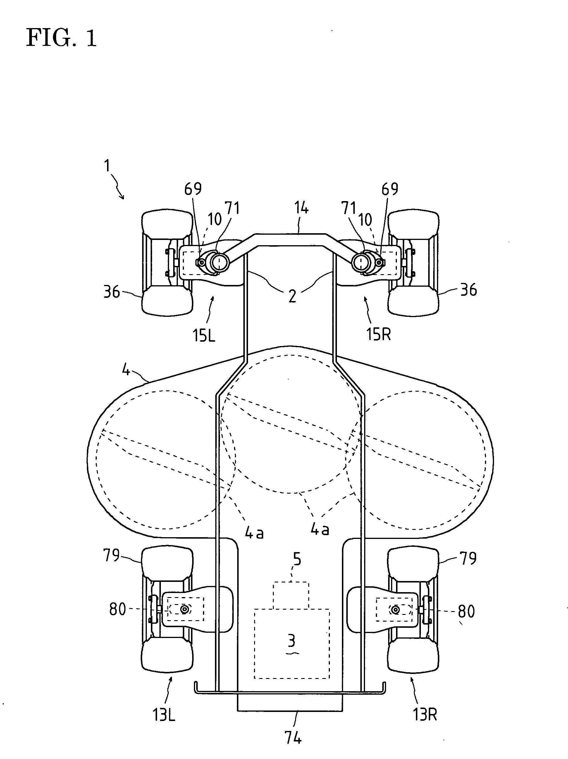
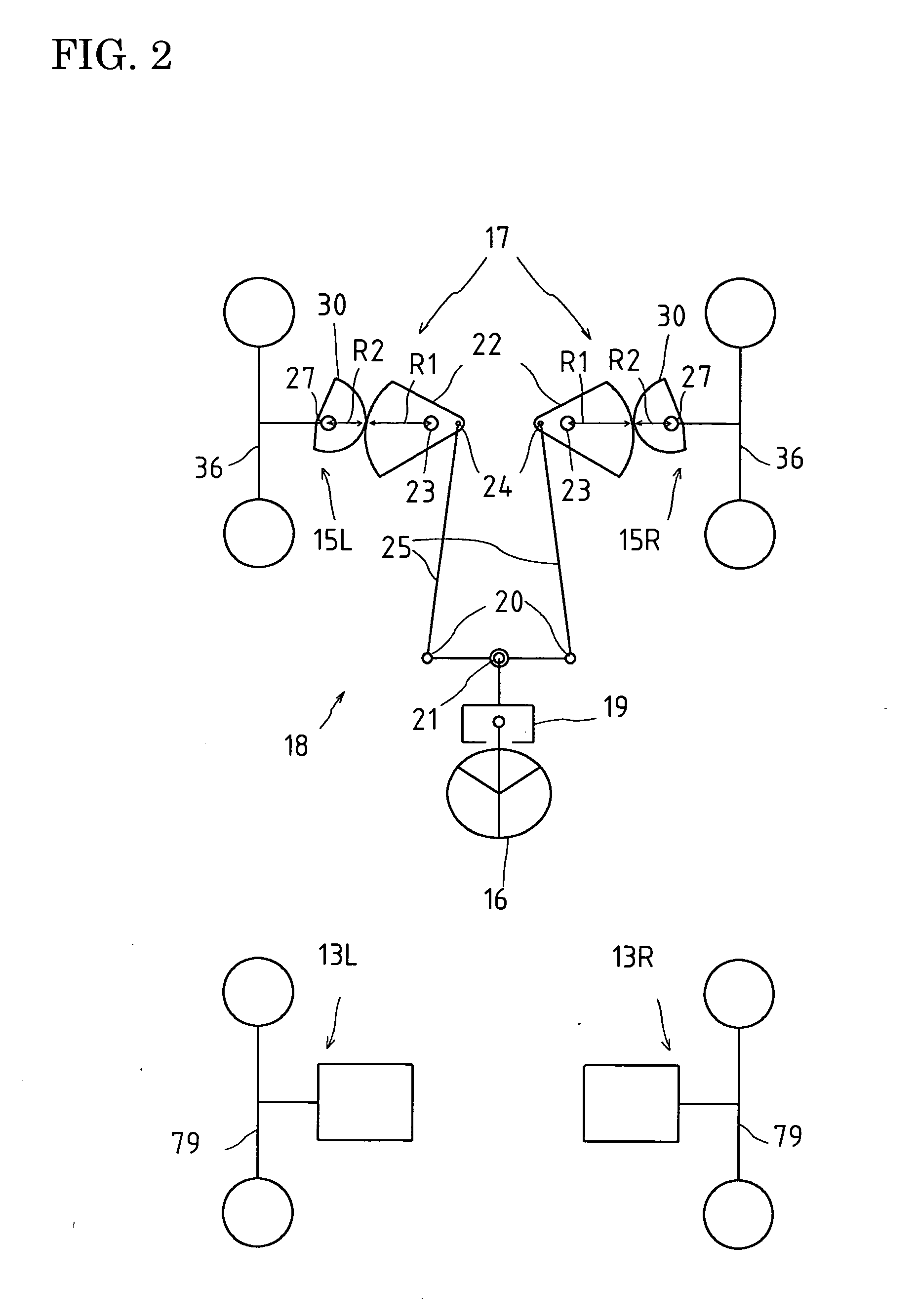
[0098] A four-wheel driving and two-wheel steering vehicle 1 shown in FIGS. 1 to 17 will be described. As shown in FIG. 1, vehicle 1 is provided with a chassis including right and left side frames 2 supporting right and left front transaxles 15L and 15R (generically named as “front transaxles 15”) and right and left rear transaxles 13L and 13R (generically named as “rear transaxles 13”), respectively.

[0099] In the following description (e.g., about each of transaxles 15 and 13), terms “proximal” and “distal” are defined with respect to the center of vehicle 1 (and later-discussed various alternative vehicles 1).

[0100] Each of front transaxles 15 supports a front wheel 36, and each of rear transaxles 13 supports a rear wheel 79. Front transaxles 15 are steerably supported by right and left side frames 2 of the vehicle chassis so that front wheels 36 serve as steerable wheels. A front cross member 14 is interposed between right and left front transaxles 15 across side frames 2 so th...


PUM


Abstract

A steerable hydraulic transaxle comprises: a kingpin relatively rotatably supported by a vehicle chassis; a housing fixed to the kingpin; a single axle disposed in the housing; a single wheel fixed onto the single axle out of the housing; and a hydraulic motor disposed in the housing so as to drive the single axle.

Description

BACKGROUND OF THE INVENTION [0001] 1. Field of the Invention [0002] The invention relates to a hydraulic transaxle, which incorporates a hydraulic motor for driving a single wheel, and is steerably supported by a vehicle chassis. The invention also relates to a four-wheel driving vehicle including the hydraulic transaxles for driving respective wheels. [0003] 2. Related Art [0004] As disclosed in U.S. patent application Publication No. 2003 / 0106725A1, there is a conventional vehicle having left and right steerable wheels linked to a steering operation device such as a steering wheel. In the conventional vehicle, according to steering, e.g., according to increase of a rotational angle of a steering wheel from its straight traveling position, turning angles of the left and right steerable wheels are increased so that the turning angle of the steerable wheel on the turning inside of the vehicle (hereinafter referred to as “inside wheel”) becomes larger than that of the steerable wheel ...

Claims


Application Information

Patent Timeline
Patent Type & Authority Applications(United States)
IPC IPC(8): B60K7/00B60K17/00B60K17/04B60K17/06B60K17/10B60K17/356B62D7/09B62D7/14B62D9/00B62D11/00
CPCB60K7/0015F16H61/452B60K17/046B60K17/105B60K17/356B60K17/358B60K2007/0038B60K2007/0092B62D7/09B62D7/142B62D9/002B62D11/005F16H59/58F16H61/427B60K17/043B60W2540/18
Inventor IRIKURA, KOJI
Owner KANZAKI KOKYUKOKI MFG
Features
  • Generate Ideas
  • Intellectual Property
  • Life Sciences
  • Materials
  • Tech Scout
  • Unparalleled Data Quality
  • Higher Quality Content
  • 60% Fewer Hallucinations
Learn More