Backlight, backlight drive device and display device

a backlight drive and display device technology, applied in static indicating devices, lighting and heating apparatuses, instruments, etc., can solve the problems of limiting the brightness obtention for displaying a television image, poor light use efficiency, and uneven illumination of the whole liquid crystal panel. to prevent uneven brightness

Active Publication Date: 2005-06-16
SATURN LICENSING LLC
View PDF15 Cites 65 Cited by
  • Summary
  • Abstract
  • Description
  • Claims
  • Application Information

AI Technical Summary

Benefits of technology

[0015] Thus, according to the present invention, by arranging the diffusion board in the position which is apart from the backlight and between the backlight and the video display unit, even when the backlight is formed by combining the plurality of the backlight units, it becomes possible to prevent brightness unevenness from occurring at a junction section of the backlight units.

Problems solved by technology

However, in a backlight of the edge light system such as mentioned above, light is incident to a side edge (a side surface) of a light guide plate, and uniform light is emitted from an upper surface side of the light guide plate to the liquid crystal panel, so that a usage efficiency of the light is bad.
For this reason, when the backlight of a conventional side edge system illuminates a large-sized liquid crystal display apparatus having a size of 20 inches or more, for example, there is a disadvantage that the whole liquid crystal panel can not be illuminated uniformly with light of high brightness.
There is a limit in obtention of the brightness for displaying a television image.
Thus, when the backlight of a large-sized liquid crystal display apparatus is realized by the side edge, there is a disadvantage that its weight becomes very heavy.

Method used


Image

  • Backlight, backlight drive device and display device
  • Backlight, backlight drive device and display device
  • Backlight, backlight drive device and display device

Examples


Embodiment Construction

[0045] Hereinafter, preferred embodiments of the present invention will be described.

[0046] In addition, the preferred embodiments will be described in the following order:

[0047] 1. Structure of Liquid Crystal Display Apparatus

[0048] 2. Backlight [0049] 2-1 Structure of Backlight [0050] 2-2 Structure of Backlight Unit [0051] 2-3 Drive Apparatus of Backlight 3. Backlight of Second Preferred Embodiment 4. Backlight of Third Preferred Embodiment

1. STRUCTURE OF LIQUID CRYSTAL DISPLAY APPARATUS

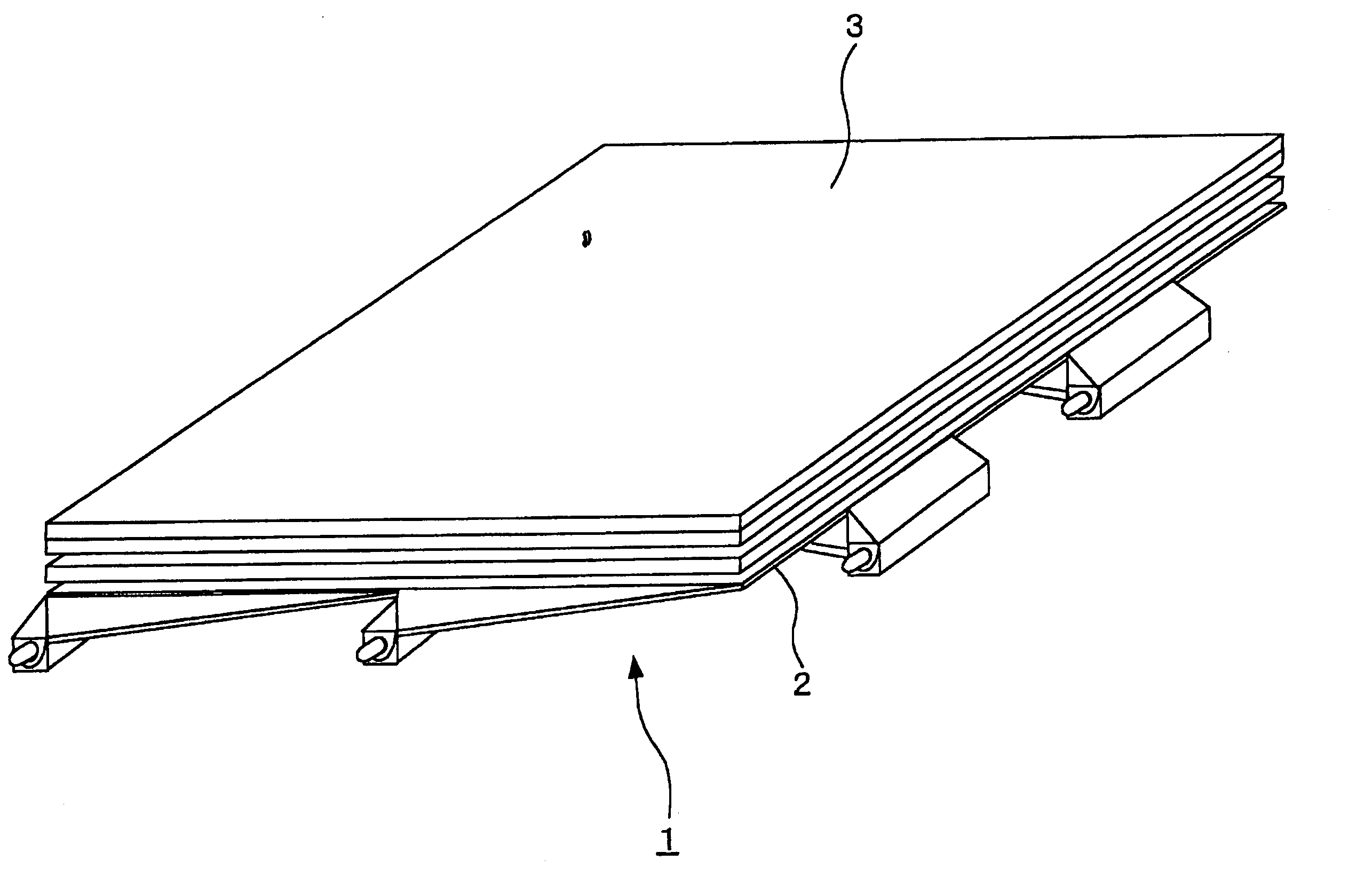
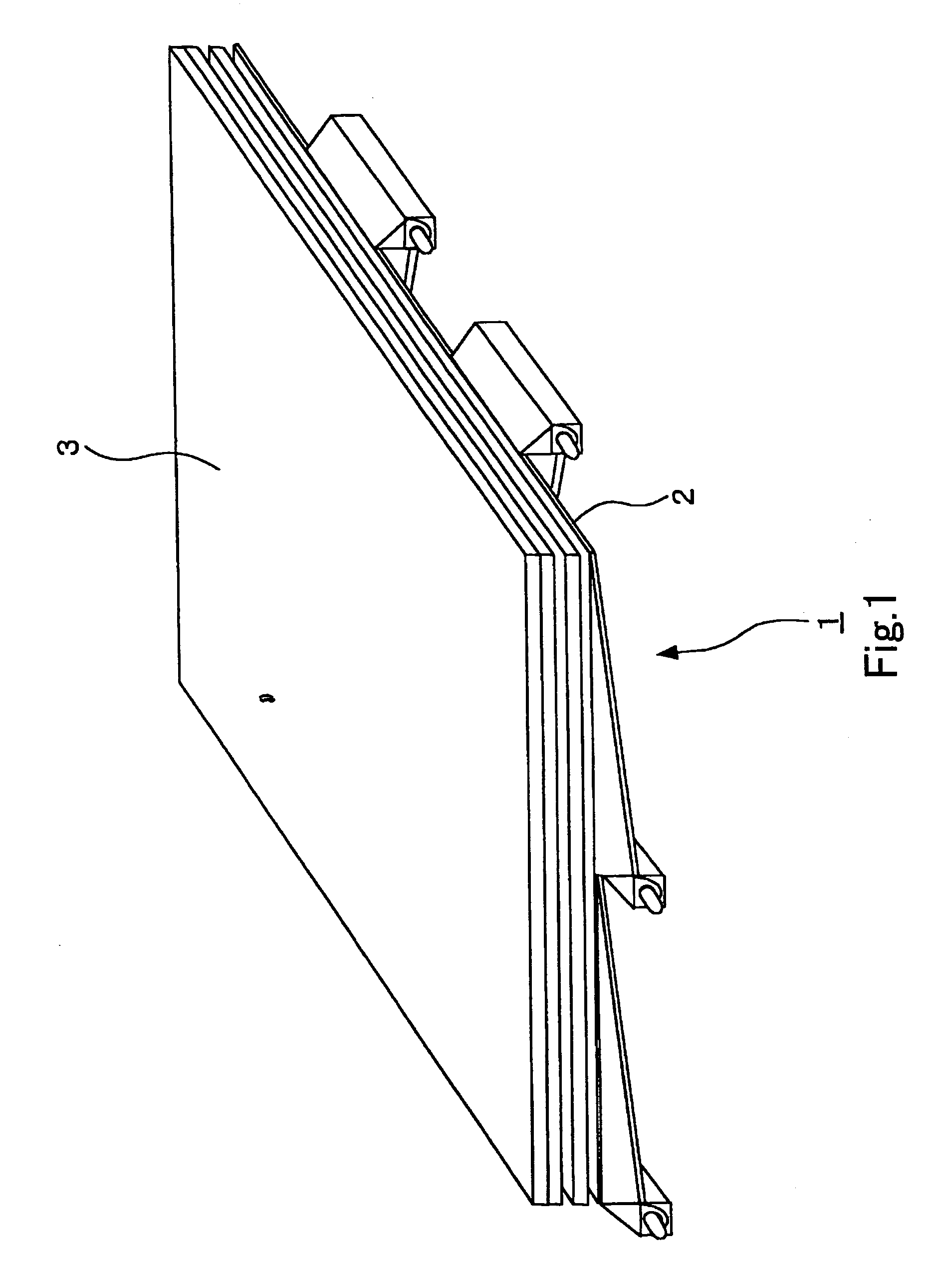
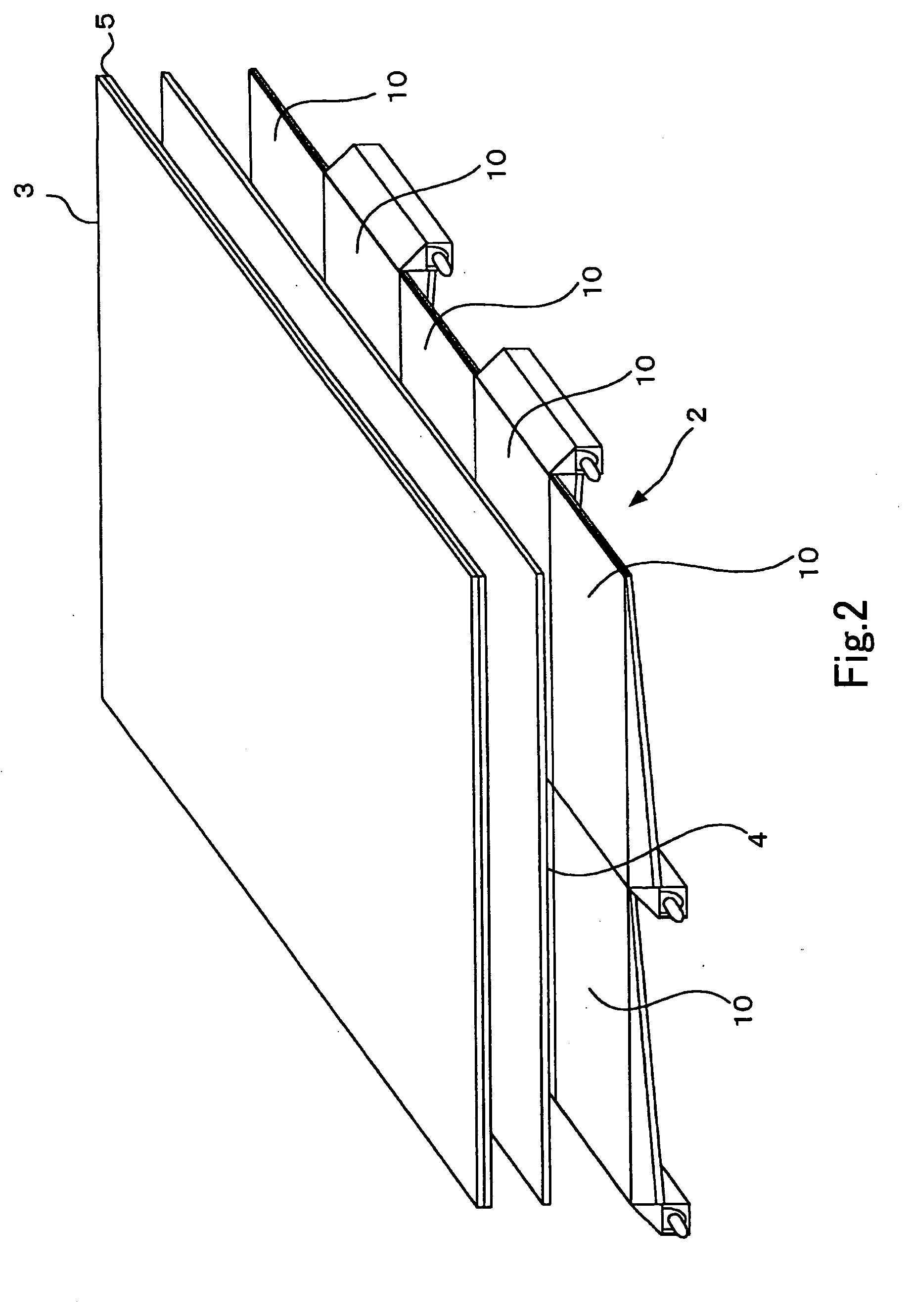
[0052] Firstly, a liquid crystal display apparatus of a preferred embodiment will be described by using FIGS. 1-3.

[0053]FIG. 1 is an overall view of the liquid crystal display apparatus of the preferred embodiment, FIG. 2 is an exploded view, and FIG. 3 is a side view.

[0054] As shown in these FIG. 1 through FIG. 3, a liquid crystal display apparatus 1 of the preferred embodiment is arranged to have a backlight 2 under a liquid crystal panel 3.

[0055] Further, between the backlight 2 and the ...


PUM

PropertyMeasurementUnit
thicknessaaaaaaaaaa
thicknessaaaaaaaaaa
sizeaaaaaaaaaa

Abstract

A proposed backlight is suitable for a large size liquid crystal display. A backlight 2 for illuminating a liquid crystal panel 3 from the rear, is formed by combining a plurality of backlight units 10, 10, . . . By providing a transparent acrylic board 4 between the backlight 2 and the liquid crystal panel 3, it becomes possible to prevent brightness unevenness from occurring at a junction section of the backlight units 10, 10, . . . , even when the backlight is formed by combining the plurality of the backlight units 10, 10, . . . .

Description

TECHNICAL FIELD [0001] The present invention relates to, for example, a backlight which illuminates a liquid crystal panel from the rear, a backlight drive apparatus which drives such a backlight, and a display apparatus which is arranged to have such a backlight. BACKGROUND ART [0002] In recent years, as for a transmissive type liquid crystal display apparatus using a liquid crystal panel which is widely spread as a display apparatus of a television receiver etc., research and development for enlarging a liquid crystal display apparatus have been performed actively. [0003] As a prior literature for realization of enlarging the liquid crystal display apparatus, a liquid crystal display apparatus is proposed in which a plurality of liquid crystal panels are joined together on the same plane and tiled so as to enlarge a liquid crystal panel, for example (Japanese Patent Application Publication No. H10-096911). [0004] In the transmissive type liquid crystal display apparatus, it is nec...

Claims


Application Information

Patent Timeline
Patent Type & Authority Applications(United States)
IPC IPC(8): G02F1/13357F21V8/00F21Y101/02F21Y103/00G02B6/00G02F1/133H05B37/02
CPCG02B6/0018G02B6/0071G02B6/0078G09G3/3426G09G2320/0233G09G2360/145G09G2360/16G02B6/0001G02F1/133G02F1/1335
Inventor FURUKAWA, NORIMASA
Owner SATURN LICENSING LLC
Why Eureka
Try Eureka