Check patentability & draft patents in minutes with Patsnap Eureka AI!

Light apparatus and method for controlling the intensity of a light emitting diode

a technology of light emitting diodes and light apparatus, which is applied in the field of providing light apparatus and methods, can solve the problems of not being able to control the bias of led transistors independently and simultaneously, the approach is not well suited to illumination applications requiring any degree of efficiency, and the biasing of led transistors using this approach is inefficient. , to achieve the effect of adjustable sensitivity of the sound sensor

Inactive Publication Date: 2005-06-16
FKA DISTRIBUTING CO LLC
View PDF4 Cites 74 Cited by
  • Summary
  • Abstract
  • Description
  • Claims
  • Application Information

AI Technical Summary

Benefits of technology

[0010] In accordance with one aspect of the present invention, each light emitting unit contains three LEDs, with each of the three LEDs emitting a different one of three primary colors. A light diffuser can be included in each light emitting unit for blending the colors provided by each LED. The array can include any number of light emitting units, typically between four and sixty-four units. The light emitting units can be square, rectangular, or any other shape. The housing can also have any shape suitable for the intended application, such as square, rectangular, or wavelike. The light apparatus can be free-standing or arranged to be mounted to a wall. Further, a remote control can be provided that includes one or more user input controls for controlling the operation of the light emitting units.
[0011] The light apparatus according to the present invention can include various features, such as a speaker and a sound sensor disposed within the housing in communication with the processor. The sound sensor can be configured to provide sound input to the processor, such that operation of the light emitt

Problems solved by technology

As such, it is not possible to control all LED transistor biases independently and simultaneously.
Biasing of transistors using this approach is inefficient because the power delivered to the LEDs is less than the power dissipated in the biasing network.
Therefore, this approach is not well suited to illumination applications requiring any degree of efficiency.
However, most approaches that employ this method make no provision for precise and rapid control over the spectrum of colors emitted.

Method used


Image

  • Light apparatus and method for controlling the intensity of a light emitting diode
  • Light apparatus and method for controlling the intensity of a light emitting diode
  • Light apparatus and method for controlling the intensity of a light emitting diode

Examples


Embodiment Construction

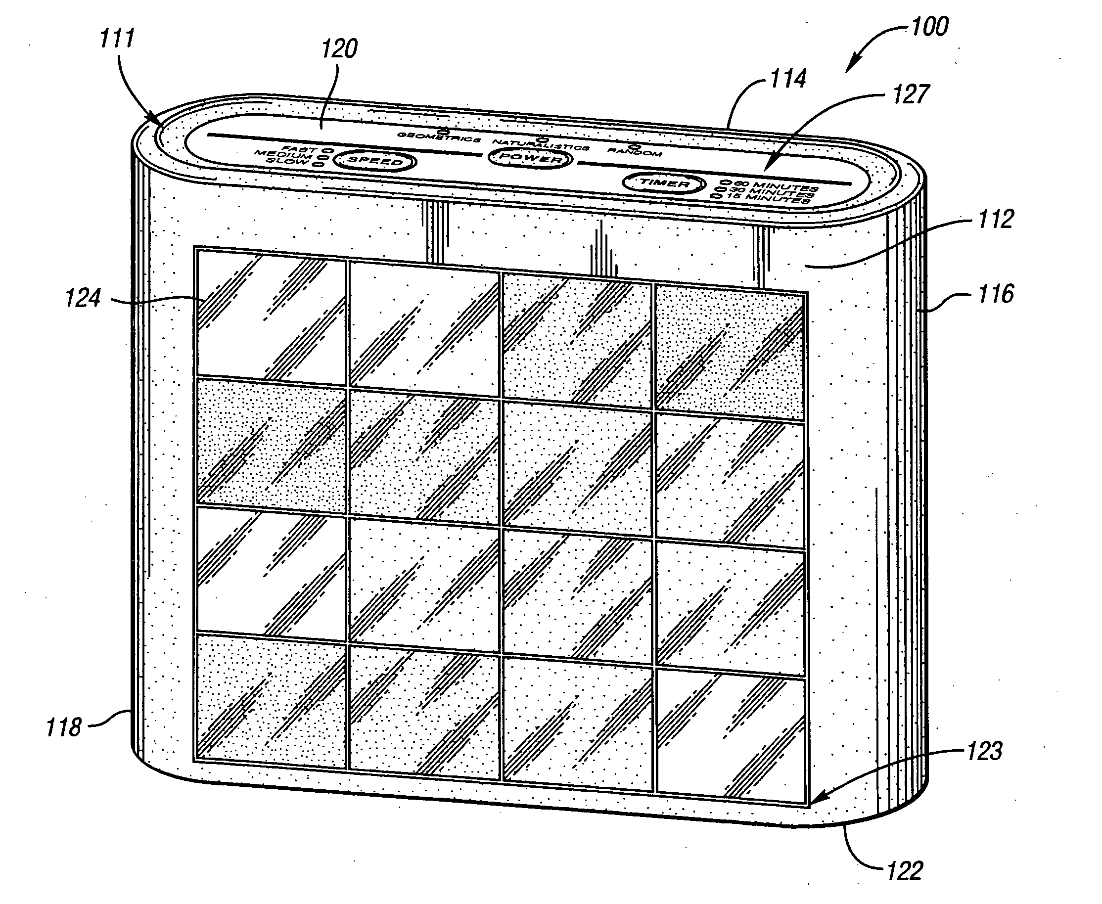
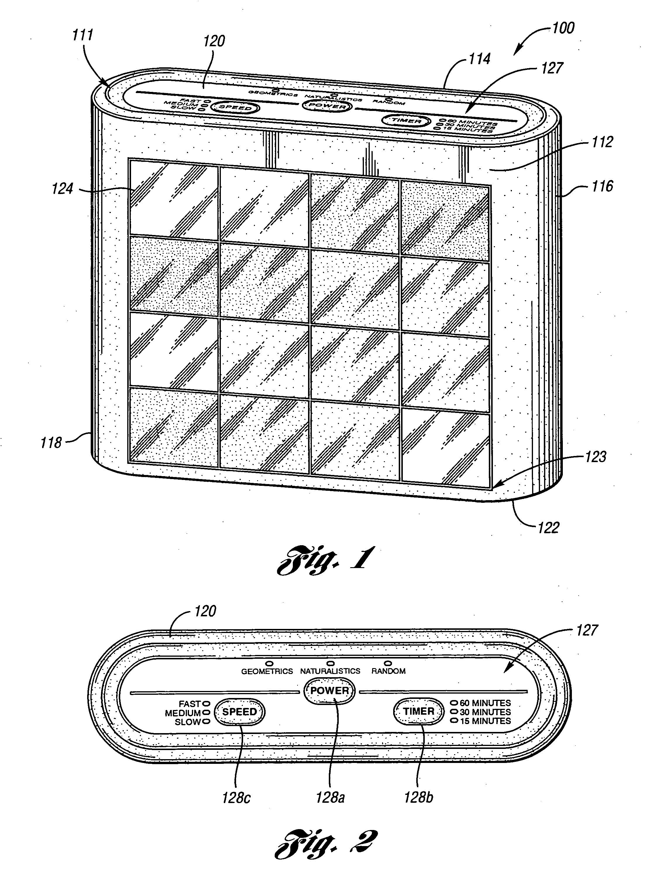
[0050] Referring first to FIG. 1, a light apparatus 100 is illustrated according to an aspect of the present invention. Light apparatus 100 has a housing 111 that generally comprises a front side 112, a back side 114, a right side 116, a left side 118, a top side 120, and a bottom side 122. As depicted in FIG. 1, front side 112, back side 114, top side 120 and bottom side 122 may be essentially flat, while right side 116 and left side 118 may be rounded for aesthetic reasons. Of course, it is understood that other shapes of housing 111 are fully contemplated according to the present invention. Light apparatus 100 is designed to stand vertically on bottom side 122, and can include a standard power cord (not shown) for plugging into a wall outlet or alternatively be battery-operated.

[0051] Front side 112 generally comprises a display area 123 having a plurality of light emitting units 124. In the example shown in FIG. 1, a total of sixteen light emitting units 124 are provided in fou...


PUM


Abstract

A light apparatus is provided having a housing and an array of light emitting units integrally formed within the housing, each light emitting unit containing at least one light emitting diode (LED). The apparatus further includes a processor in communication with the LEDs in each light emitting unit, and user input controls in communication with the processor for controlling the light emitting units, such that a light color displayed by each light emitting unit can vary with time. Methods for controlling the intensity of an LED are also provided.

Description

CROSS-REFERENCE TO RELATED APPLICATIONS [0001] This application claims the benefit of U.S. provisional application Ser. No. 60 / 529,777 filed Dec. 16, 2003.BACKGROUND OF THE INVENTION [0002] 1. Field of the Invention [0003] The present invention relates to a light apparatus and method for providing a light display using LEDs. [0004]2. Background Art [0005] Combining light of one color with light of another color will result in the creation of a third color. For example, red, blue, and green lights can be combined in different proportions or intensities to create almost any color in the visible spectrum. Light emitting diodes (LEDs) of different colors may be used for this purpose. It would be desirable to apply LED lighting technology to an application useful for home sensory therapy. It would further be desirable to have an affordable lighting device based on LED technology that creates a relaxing, stimulating, and entertaining light show for a user. [0006] One conventional approach...

Claims


Application Information

Patent Timeline
IPC IPC(8): F21S10/02G04G9/04
CPCF21S10/02F21Y2101/02G04G9/04H05B33/0842Y02B20/46H05B37/0218H05B37/0236H05B37/029H05B33/0857F21Y2115/10H05B45/10H05B45/20H05B45/325H05B47/11H05B47/12H05B47/155Y02B20/40
Inventor CHUEY, MARK D.CHUNG, STEPHENLEV, MORDECHAIFERBER, ROMAN S.
Owner FKA DISTRIBUTING CO LLC
Features
  • R&D
  • Intellectual Property
  • Life Sciences
  • Materials
  • Tech Scout
  • Unparalleled Data Quality
  • Higher Quality Content
  • 60% Fewer Hallucinations
Learn More