
Handover method and handover apparatus

a terminal and handover technology, applied in the field of handover methods and handover apparatuses for fast moving terminals, can solve the problems of affecting the quality of ipv6 streams of mobile nodes, and unable to receive ip packets at the new node, so as to reduce handover latency and packet losses

Inactive Publication Date: 2005-06-16
SAMSUNG ELECTRONICS CO LTD
View PDF4 Cites 75 Cited by
  • Summary
  • Abstract
  • Description
  • Claims
  • Application Information

AI Technical Summary

Benefits of technology

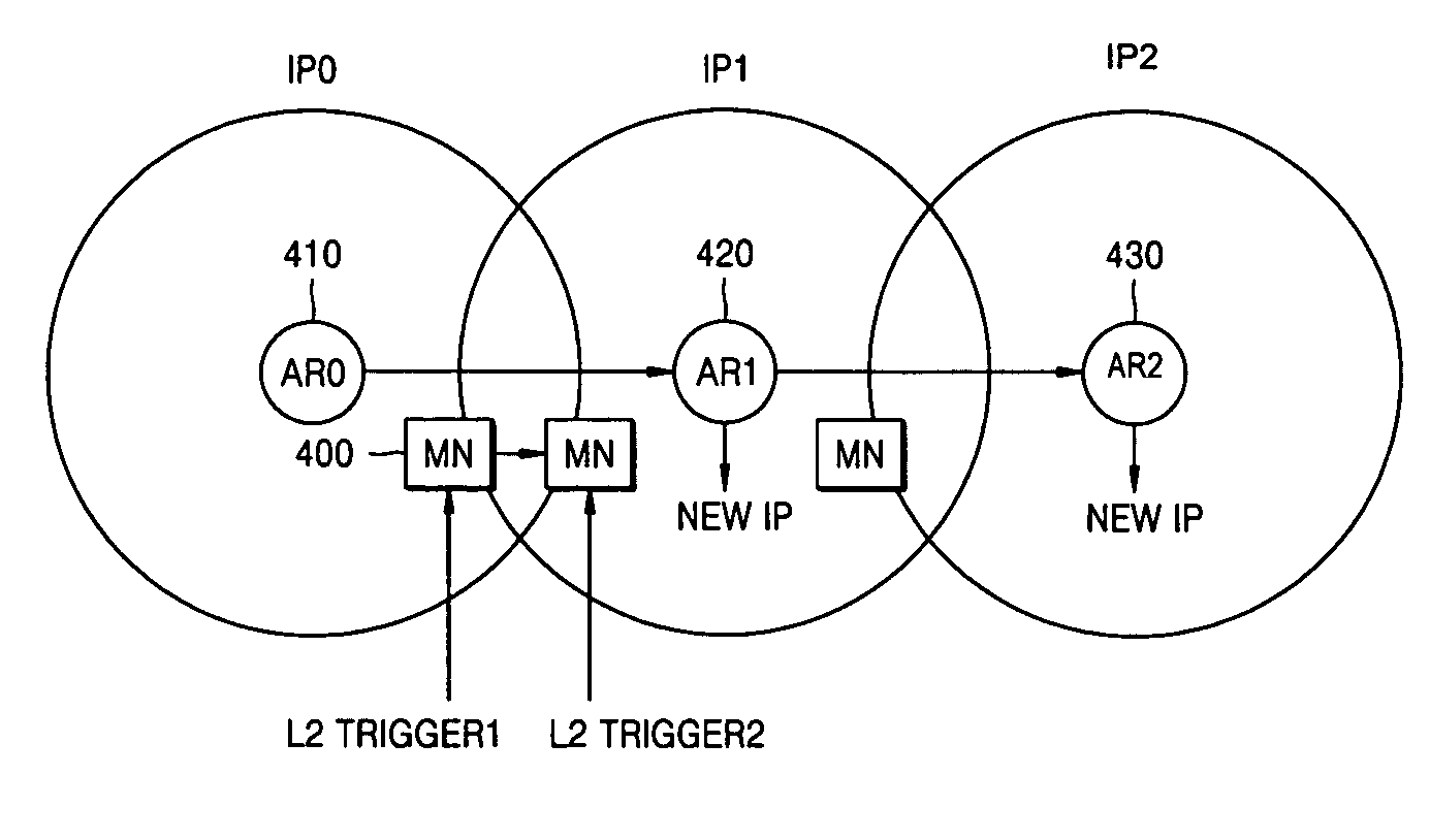
[0028] In an aspect of the present invention, a handover method and handover apparatus which can reduce handover latency and packet losses for a fast-moving terminal in a mobile IPv6 environment are provided.

Problems solved by technology

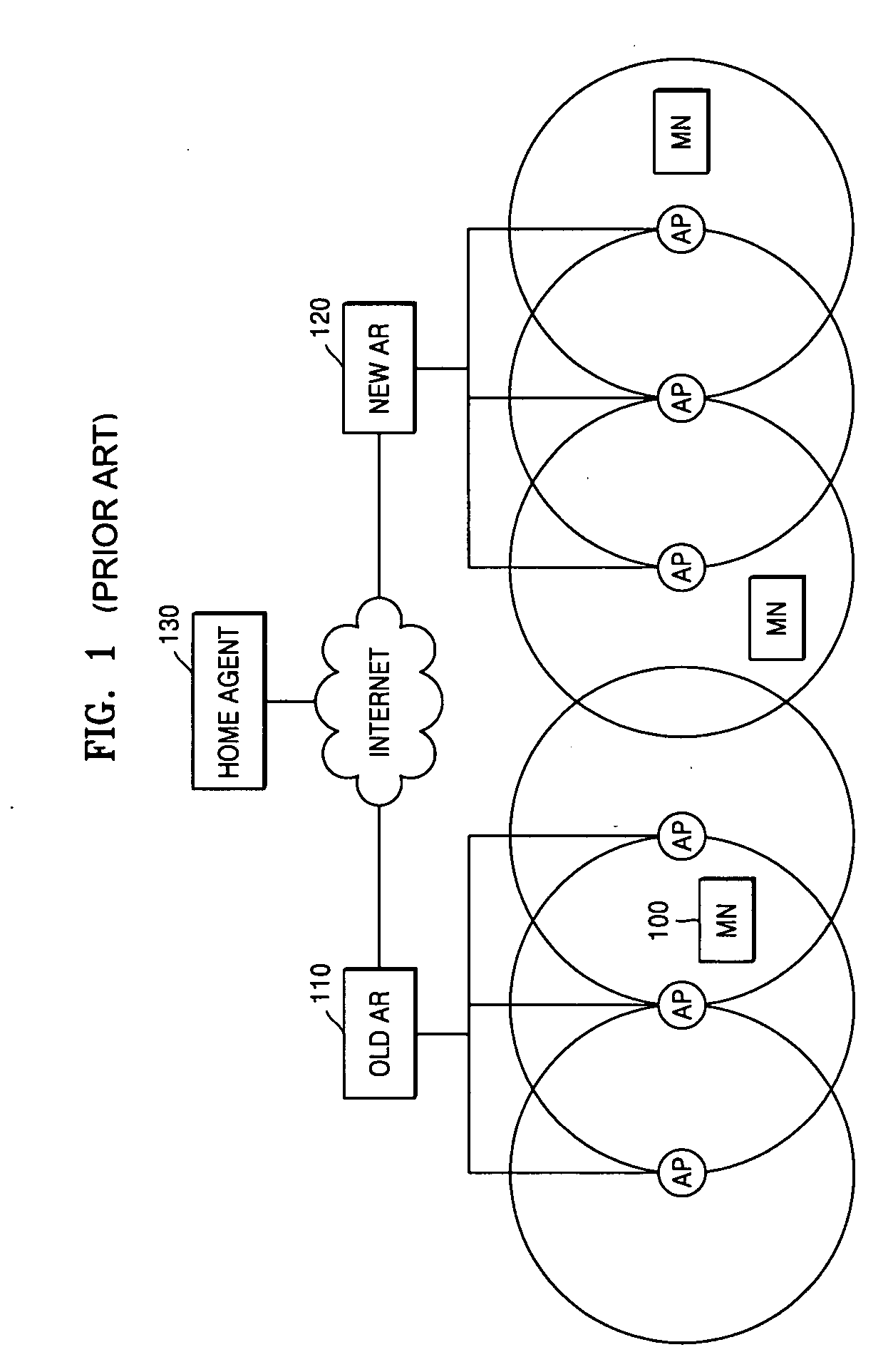
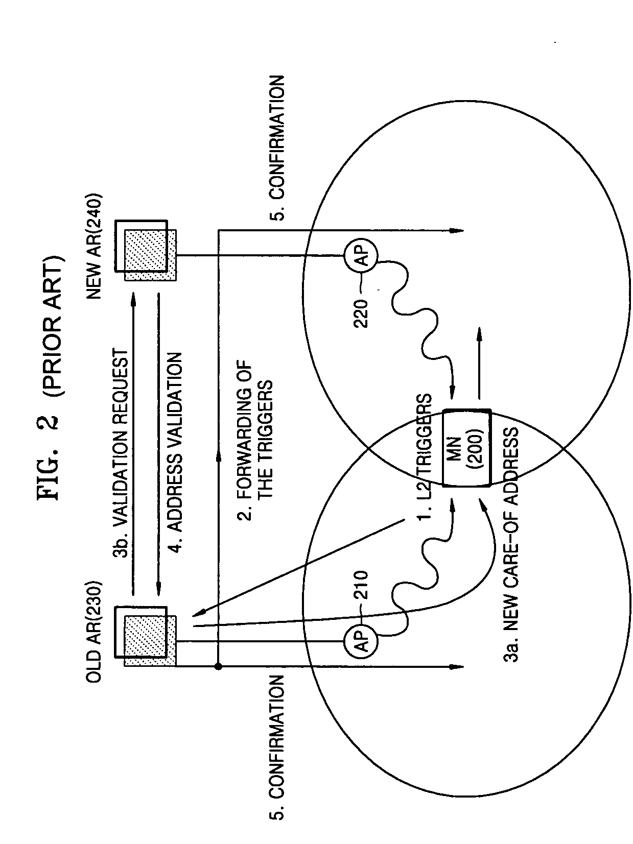
However, the mobile node is unable to receive an IP packet at the new point unless the handover is finished.
Actually, this handover latency may be too long in real time multimedia applications.
In many cases, this handover latency may greatly degrade the quality of IPv6 streams of a mobile node.
Since the drawbacks are caused by the fact that the conventional handover method performs handover by using only layer 3 information, the fast handover method is intended to more actively perform a handover process by using layer 2 information.
However, it cannot solve all the problems and in particular, in a terminal moving at a high speed, there are additional problems.
Also in the case of tunnel-based handover, in a situation where there are many fast-moving terminals, the load to form a channel becomes very large in each router.
In addition, because a router should manage channel information for each mobile terminal, the load to a router becomes more serious on a freeway or high-speed train where fast-moving terminals are crowded.

Method used


Image

  • Handover method and handover apparatus
  • Handover method and handover apparatus
  • Handover method and handover apparatus

Examples


Embodiment Construction

[0066] Reference will now be made in detail to the embodiments of the present invention, examples of which are illustrated in the accompanying drawings, wherein like reference numerals refer to the like elements throughout. The embodiments are described below to explain the present invention by referring to the figures.

[0067] In an aspect of the present invention, the care-of address (CoA) establishing process from automatic formation to duplicated address detection (DAD), which takes a significant amount of time in a handover process, is performed in advance so that immediately after an L3 handover occurs, a mobile node can use a new CoA.

[0068] In addition, considering that fast-moving terminals usually have predetermined directivity, a bicasting technique which is used mainly for layer 2 in the conventional applications is expanded by applying a layer 3 tunneling technique in an aspect of the present invention. That is, in order to establish a route to a destination based on the...


PUM


Abstract

Communication handover methods and apparatuses for use in an environment involving terminals having mobile nodes moving at a high speed. The handover method includes actively requesting handover to an access router based on the moving speed of a mobile node. The handover methods and apparatuses reduce handover latency and packet losses in a handover process of a terminal moving at a high speed.

Description

CROSS-REFERENCE TO RELATED APPLICATIONS [0001] This application claims priority of Korean Patent Application No.2003-89362, filed on Dec. 10, 2003 in the Korean Intellectual Property Office, the disclosure of which is incorporated herein by reference. BACKGROUND OF THE INVENTION [0002] 1. Field of the Invention [0003] The present invention relates to a handover method and apparatus in a mobile Internet protocol (IP) version 6 (IPv6) environment, and more particularly, to handover methods and handover apparatuses for a fast-moving terminal in a mobile IPv6 environment. [0004] 2. Description of the Related Art [0005] Recently, wireless network access has been a field of increasing interest because it allows nodes to move at a reasonable speed during communications and accessing a network. [0006]FIG. 1 is a reference diagram to explain the structure of the prior art IPv6 wireless network. Mobile IPv6 is designed to manage movement of a mobile node among IPv6 networks. [0007] Referring ...

Claims


Application Information

Patent Timeline
IPC IPC(8): H04B7/26H04W36/32H04W80/00
CPCH04W80/00H04W36/32H04W36/324H04W36/38
Inventor LEE, MIN-HOKIM, PYUNG-SOO
Owner SAMSUNG ELECTRONICS CO LTD
Learn More