
Handover method and device for mobile node in wireless LAN

Inactive Publication Date: 2008-02-05
SAMSUNG ELECTRONICS CO LTD
View PDF15 Cites 7 Cited by
  • Summary
  • Abstract
  • Description
  • Claims
  • Application Information

AI Technical Summary

Benefits of technology

[0020]The present invention provides a handover method and device for a mobile node in a wireless LAN environment, which are capable of reducing handover latency.
[0025]In order to reduce handover latency, the present invention allows some steps in a handover process to be carried out before an L2 trigger of a layer 2 occurs rather than putting off all steps of the handover process until an L2 trigger occurs.
[0026]In other words, a mobile node predicts which access router will be the next access router, i.e., a NAR, through a beacon scanning process performed in layer 2 and obtains information on the predicted access router before entering a new network. Therefore, after the mobile node enters the new network, it does not need to hasten to obtain NAR information because it already has the NAR information. As a result, this process helps reduce handover latency considerably.

Problems solved by technology

Since the Internet has grown to become a major component of an information infrastructure, an increasing number of problems have emerged due to a sharp increase in the number of users and Internet-related devices.
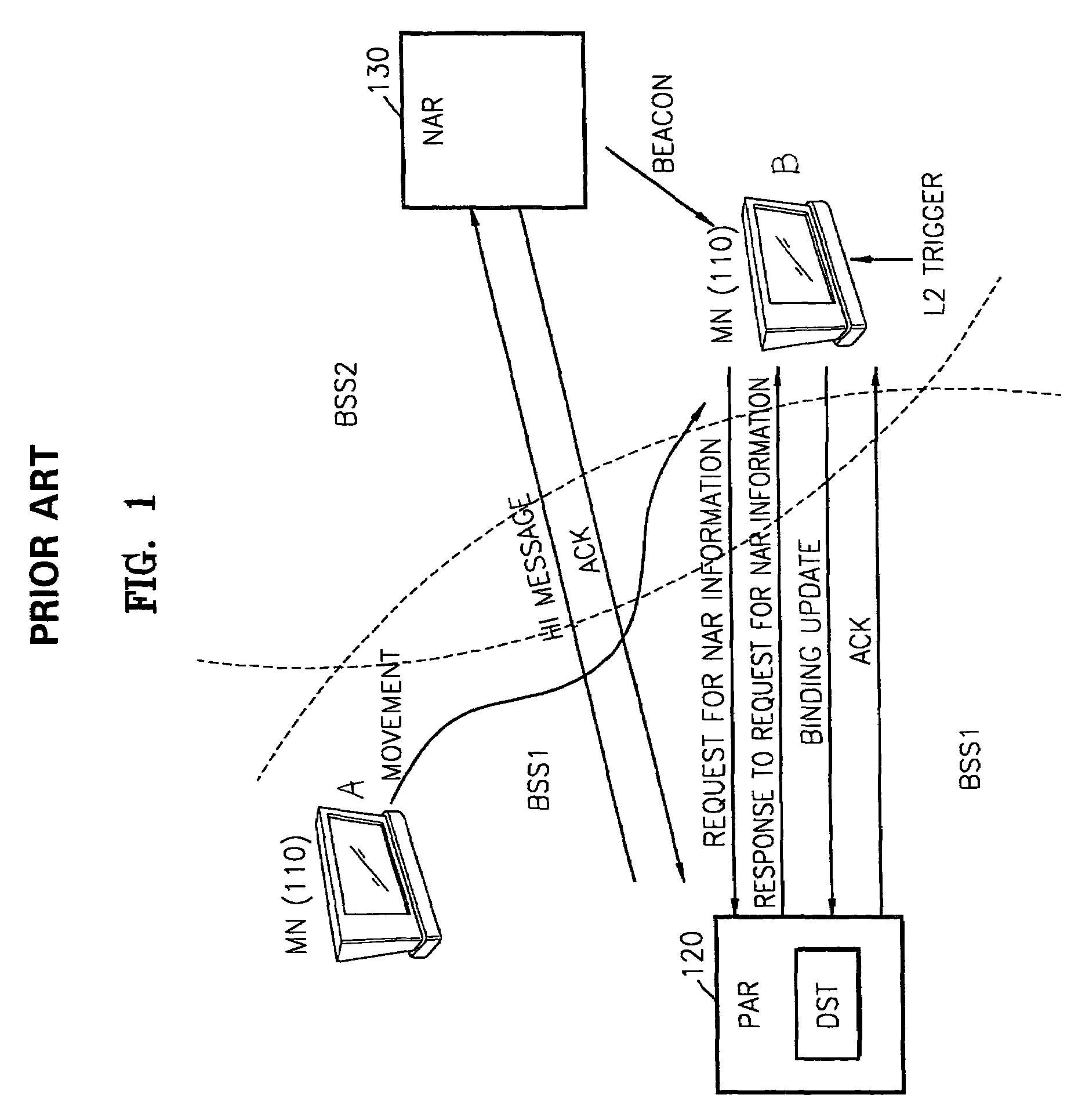
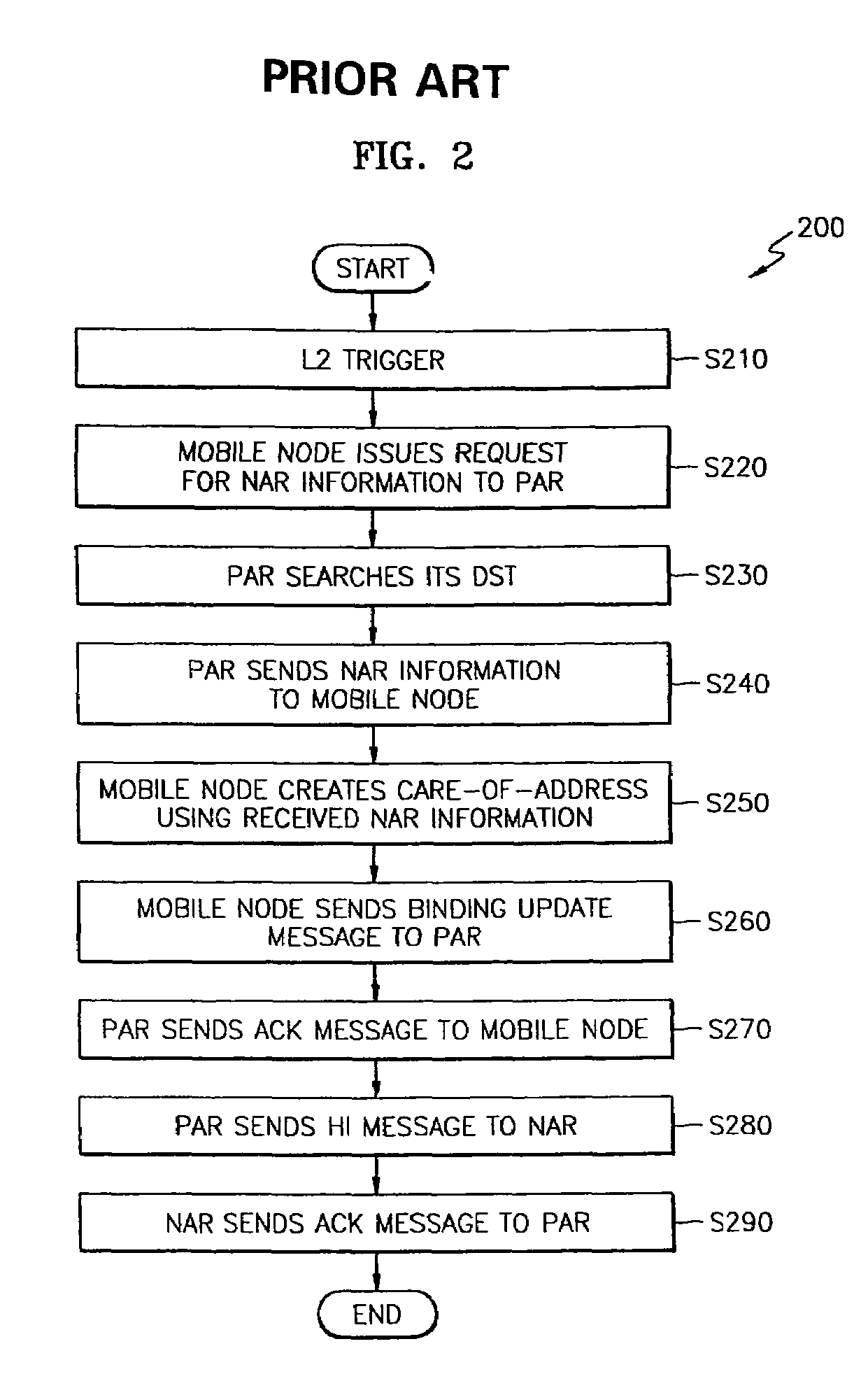
However, since the conventional handover process takes a considerable amount of time, the amount of time for which transmission of packets from an IP layer is delayed due to handover, i.e., handover latency, inevitably increases, thereby making it almost impossible to apply the conventional handover technique to real-time communications, such as video phone communications, video conferences, or transmission of moving images.
However, because the prefix information is contained in the beacon message and transmitted to the user terminal on the beacon message, the size of the beacon message inevitably is large.

Method used


Image

  • Handover method and device for mobile node in wireless LAN
  • Handover method and device for mobile node in wireless LAN
  • Handover method and device for mobile node in wireless LAN

Examples


Embodiment Construction

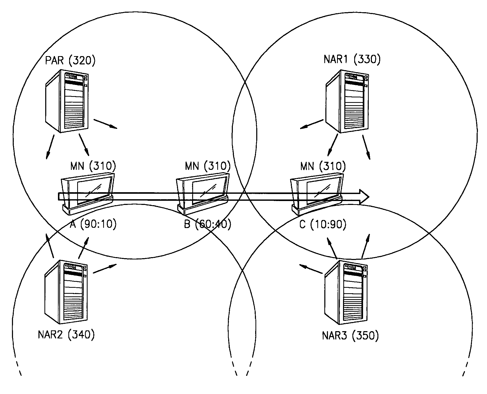
[0034]FIG. 3 is a diagram illustrating a high-speed handover method in a wireless LAN environment, according to an exemplary embodiment of the present invention.

[0035]Let us assume that a mobile node 310 moves from point A to point C via point B. Then the mobile node 310 is predicted to receive beacon signals from previous access router (PAR) (320) and new access routers (NAR)1 (330), NAR2 (340), and NAR3 (350). When the mobile node 310 is located at point A, it can receive only weak beacon signals from NAR2 (340) and NAR3 (350). Therefore, let us assume that the mobile node 310, located at point A, receives beacon signals only from PAR (320) and NAR1 (330) with an intensity ratio of 90:10. As the mobile node 310 moves closer to point C, the intensity of the beacon signal received from PAR (320) weakens but the intensity of the beacon signal received from NAR1(330) strengthens.

[0036]While moving from one place to another, the mobile node 310 can predict which access router will be a...


PUM


Abstract

A handover method and a handover device for a mobile node in a wireless LAN environment are provided. The handover method involves a) scanning beacon signals transmitted from neighboring access routers while a mobile node moves from place to place; b) predicting a new access router (NAR) based on the beacon scanning results; c) obtaining information on the predicted NAR before an L2 trigger of a link layer occurs; and d) carrying out binding update using the information on the predicted NAR when the L2 trigger of the link layer occurs.

Description

BACKGROUND OF THE INVENTION[0001]This application claims the priority of Korean Patent Application No. 2002-82385, filed on Dec. 23, 2002, in the Korean Intellectual Property Office, the disclosure of which is incorporated herein in its entirety by reference.FIELD OF THE INVENTION[0002]The present invention relates to a handover method and device for a mobile node.DESCRIPTION OF THE RELATED ART[0003]Since the Internet has grown to become a major component of an information infrastructure, an increasing number of problems have emerged due to a sharp increase in the number of users and Internet-related devices. Accordingly, an internet protocol version 6 (IPv6) has been developed to resolve problems, such as a shortage of IP addresses, and achieve more efficient routing, better security, better mobility, and better quality of service (QoS), and its commercialization is now under way.[0004]A mobile IPv6 device, which provides functions mainly based on IPv6, is predicted to exhibit bett...

Claims


Application Information

Patent Timeline
IPC IPC(8): H04Q7/20H04Q7/00H04Q7/24H04L12/46H04L12/28H04L29/06H04W36/00H04W36/36H04W48/16H04W80/04
CPCH04W36/36H04W36/0011H04W48/16H04W80/04H04W84/12H04W36/00837H04W36/12H04W8/04H04W36/362
Inventor LEE, JAE-HWANGKIM, PYUNG-SOOKIM, SUN-WOO
Owner SAMSUNG ELECTRONICS CO LTD
Learn More