Packet switch for switching variable length packets in the form of ATM cells

a packet switch and variable length technology, applied in the field of packet switches, can solve the problems of packets not being forwarded to the same output, packet delay time in message transfer, and inability to guarantee factors in communications performance, and achieve the effect of small delay time and simple qos (quality of service)

Inactive Publication Date: 2005-06-14
HITACHI LTD
View PDF9 Cites 123 Cited by
  • Summary
  • Abstract
  • Description
  • Claims
  • Application Information

AI Technical Summary

Benefits of technology

[0015]Another object of this invention is to provide node equipment and a packet switch for receiving variable length packets of different service classes and in particular capable of shortening the relay delay time by controlling the forwarding of packets according to the order of priority in the case of receiving packets of service classes requiring real time handling.
[0017]Yet another object of this invention is to provide node equipment and a packet switch capable of achieving a simple QoS (Quality of service) function.
[0018]A further object of this invention is to provide node equipment and a packet switch that do not discard the packet due to congestion and are capable of relaying packets with a high order of priority to an output line with a small delay time.
[0020]According to the above configuration of the present invention, when congestion for instance has occurred within the packet switch, by notifying the congested status to each interface and by selectively controlling the forwarding of remaining cells to the congested paths by said mentioned controller according to the order of priority of each cell in the queue, a worsening of the congestion can be avoided.

Problems solved by technology

The IP network makes a best possible effort to transfer the message to the destination terminal but cannot guarantee factors in communications performance such as delay time in the message transfer.
However, in node equipment of the conventional art, once the forwarding operation of packet data to an output line interface begins, other IP packets cannot be forwarded to the same output line interface until the forwarding of the previous packet has been completed, because the forwarding operation of data from each input line interface to a switching unit or to one of the output line interfaces is performed in units of variable length packets.
In particular, when a large data length of IP packet is being forwarded, there creates the problem of a large relay delay for subsequent packets.

Method used


Image

  • Packet switch for switching variable length packets in the form of ATM cells
  • Packet switch for switching variable length packets in the form of ATM cells
  • Packet switch for switching variable length packets in the form of ATM cells

Examples


first embodiment

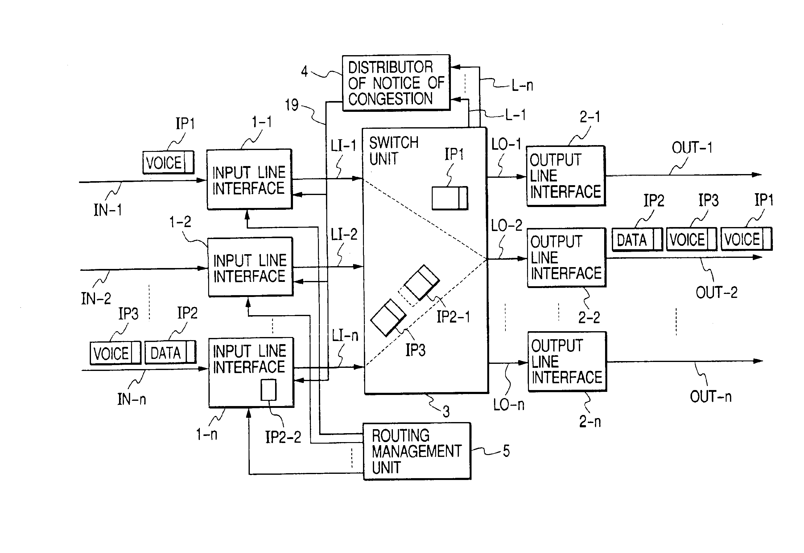
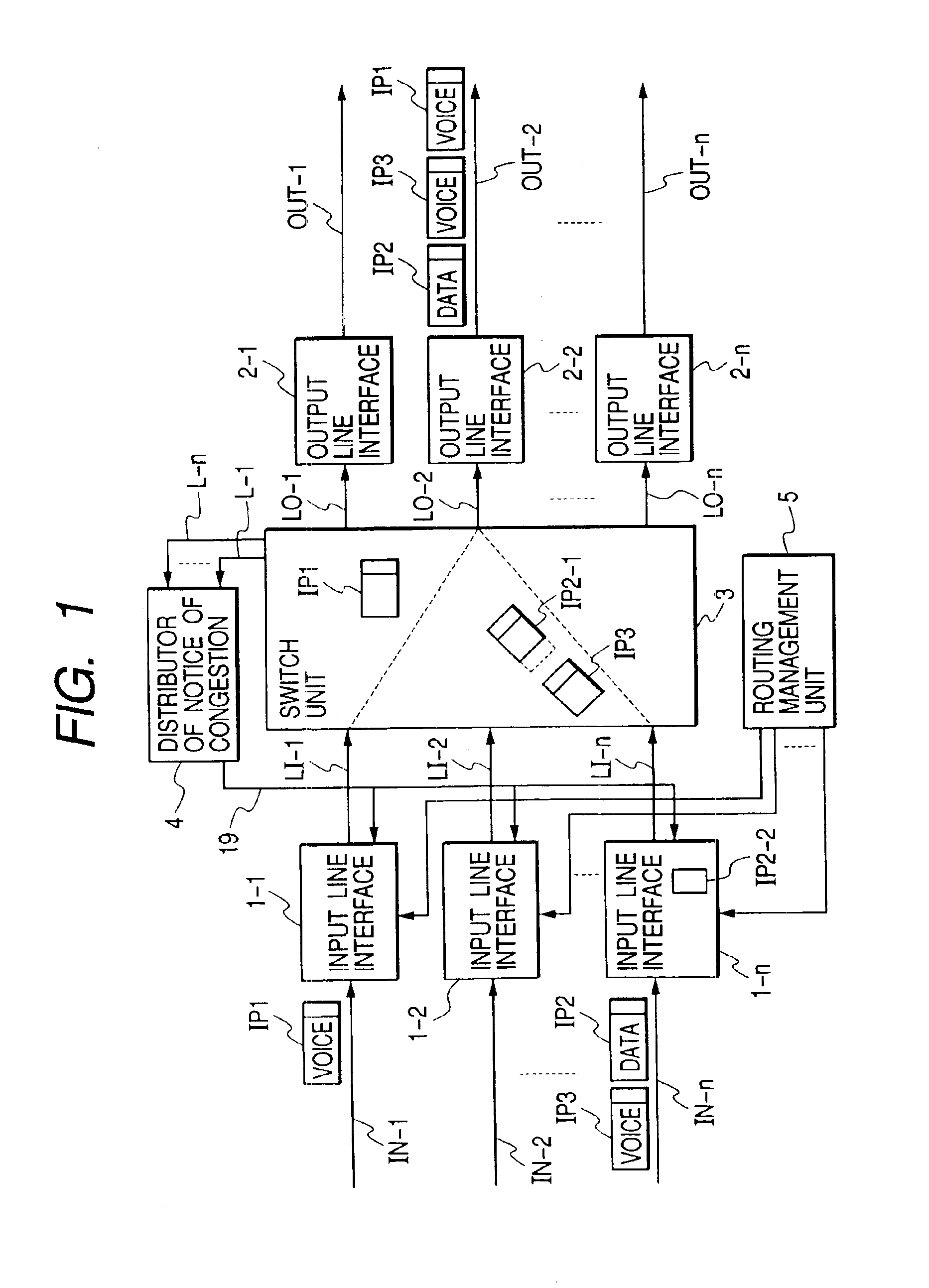
[0044]FIG. 1 shows the packet switch of this invention.

[0045]A packet switch comprises a plurality of input line interfaces 1 (1—1 to 1-n) connected to input lines IN (IN-1 to IN-n) for converting the IP packet received from the input lines to one or more fixed length cells and sending the cells to switch input ports LI (LI-1 to LI-n); a switching unit 3 having a plurality of input ports LI-1 to LI-n and output ports LO-1 to LO-n and switching the input cells from the input ports to any one of the output ports specified by the routing information contained in each of the cell headers; a plurality of output line interfaces 2 (2-1 to 2-n) each connected to one of the switch output ports to restore the original IP packet from the cells received from the output port and send that IP packet to the output line OUT (OUT-1 to OUT-n) associated therewith; a congestion notifier unit (a distributor of notice of congestion) 4 to inform each input line interface 1 of the congestion status in the...

second embodiment

[0088]FIG. 9 shows the packet switch of this invention.

[0089]This embodiment employs a packet switch having no buffer memory to form cell queues as the switch unit 3A, and the congestion status is detected at each output line interface 2′(2′-1 to 2′-n) and informed to each input line interface 1 (1—1 to 1-n) via the congestion notifier 4. The same configuration as shown for the first embodiment in FIG. 2 can be adopted for each input line interface 1.

[0090]FIG. 10 shows an example of the configuration of the switching unit 3A in FIG. 9.

[0091]The switching unit 3A is of a crosspoint type comprising of a plurality of cell transfer controllers 33 (33-1 through 33-n) installed for each of the output ports LO-1 through LO-n. Each cell transfer controller 33 comprises a selector 331 connected to a plurality of input ports LI-1 through LI-n for selecting one of the input ports to pass an input cell from the selected input port to the output port, and a header analyzer 332 for analyzing the...

third embodiment

[0098]the packet switch of this invention is explained next.

[0099]FIG. 12 shows a communication network adaptable for use with the packet switch N1 (N1-1, N1-2) of this embodiment.

[0100]When for instance forwarding an IP packet generated from one of terminals (t) through (v) connected to an IP network 91 to another one of terminals (w) through (z) connected to an IP network 92 at the other end as shown in the FIG. 12, the IP packet is relayed through an intermediate network 90 comprising a plurality of nodes (packet switches) between the source IP network 91 and the destination IP network 92. In the intermediate network 90, if the aforementioned packet switch of this invention is applied a path including the nodes N1-1, N2, N1-2 for performing IP packet communication, transmission delays may become a problem because of the repetitive conversion of IP packets to ATM cells and vice versa at each node. However, if communication is performed between nodes with ATM cells such as in the p...


PUM


Abstract

A packet switch which includes input line interfaces for converting variable length packets received from input lines to fixed length cells, a switch unit for switching said packets in cell units, output line interfaces for converting output cells from the switching unit to variable length packets and transmitting the variable length packets over output lines. Each of the input line interfaces has a cell output controller for queuing the fixed length cells for each output line according to the degree of priority of the cells, and for selectively outputting the stored cells in the queues in order of priority, thereby to suppress the transmission of cells with a low priority during the times of congestion.

Description

BACKGROUND OF THE INVENTION[0001]1. Field of the Invention[0002]This invention relates to a packet switch and in particular to a packet switch in communication networks for switching variable length packets such as typified by IP (Internet protocol) packets.[0003]2. Description of Related Art[0004]In recent years, in Internet Protocol (-hereafter referred to as IP), message transfer or forwarding is performed by packets called IP datagrams (hereafter referred to as IP packets). In a conventional IP network, node equipment such as a router installed within the network, transfers a received packet to adjacent node equipment along a selected path according to the respective destination addresses in the order that the packet was received. The IP network makes a best possible effort to transfer the message to the destination terminal but cannot guarantee factors in communications performance such as delay time in the message transfer.[0005]In each node within the IP network, the IP heade...

Claims


Application Information

Patent Timeline
Patent Type & Authority Patents(United States)
IPC IPC(8): H04J3/14H04L12/56H04L12/28H04Q3/00H04L47/30H04L47/43H04L47/6275
CPCH04L12/5601H04L49/608H04L2012/5683H04L2012/5651
Inventor NAKAYAMA, KAORIWADA, MITSUHIROKANNO, TAKAYUKIYAMAMOTO, NOBUYUKIMATSUOKA, MAKOTOFUTAMI, YUSHOKOZAKI, TAKAHIKO
Owner HITACHI LTD
Why Eureka
Try Eureka