
Distributed processing of high level protocols, in a network access server

a network access server and high-level protocol technology, applied in the field of data communication, can solve the problems of inefficiency and loss of throughput, extremely heavy processing load on one computing platform, and introduce latencies and delays in the call routing process

Inactive Publication Date: 2001-10-16
UTSTARCOM INC
View PDF22 Cites 131 Cited by
  • Summary
  • Abstract
  • Description
  • Claims
  • Application Information

AI Technical Summary

Benefits of technology

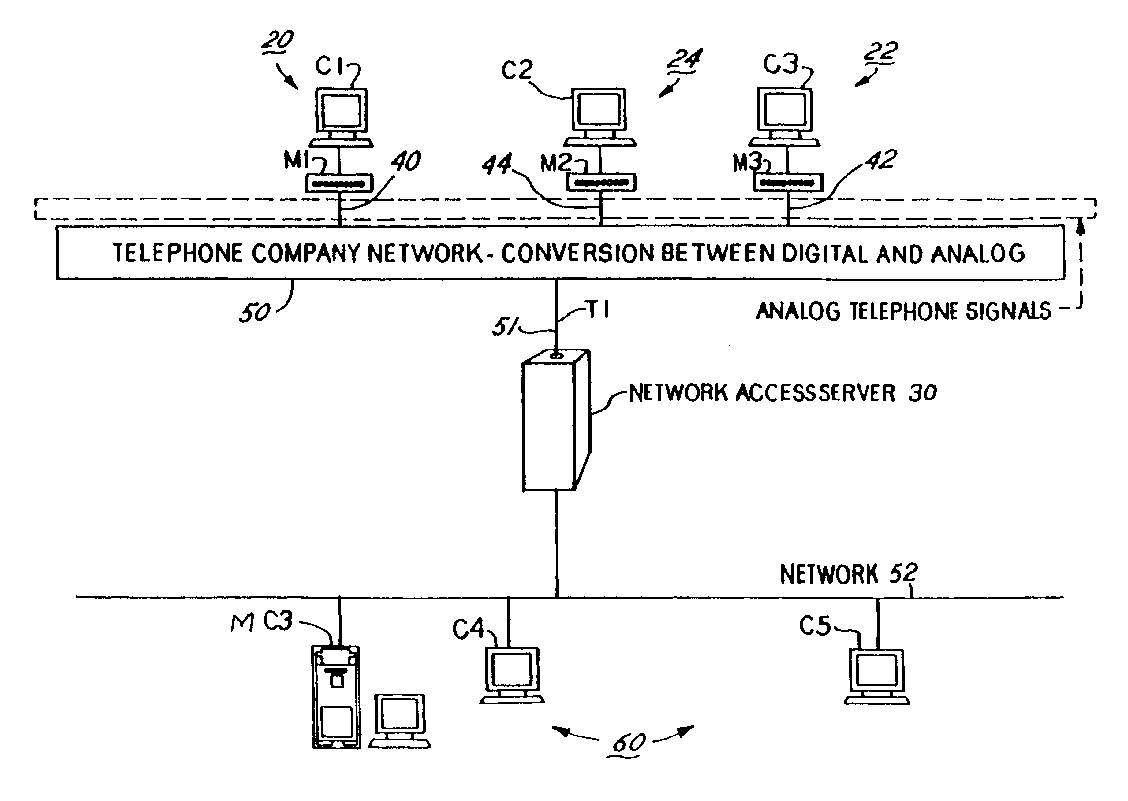
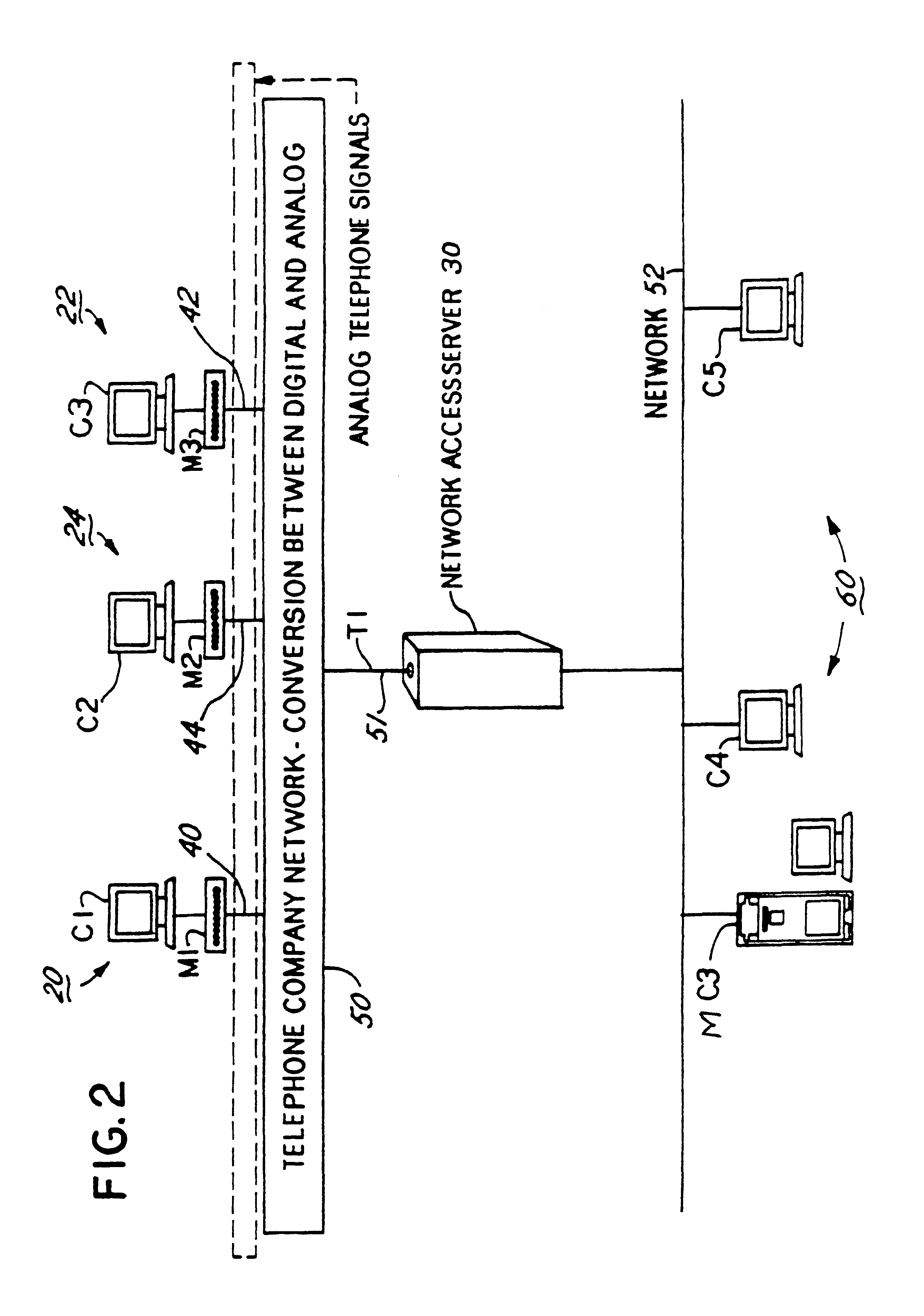
In the prior art, when an application software routine at the network access server gateway creates a PPP (or SLIP) frame, it checks each byte, looking for a byte that is a control character. If the application finds a control character, a PPP Escape character (or SLIP Escape character) is stuffed into the data stream. Then, the original control character is translated to a transparent character and stuffed into the data stream. This usually requires two buffers, because extra characters are added. For PPP frames, while the application is looking at each byte of the frame, it must also calculate the FCS. When the application receives a PPP (or SLIP) frame, it must do the reverse of the above process. In some network access servers, such as the Total Control network access server of 3Com Corporation, a large number of modems may be active at any one time. This means that the gateway computing platform in the network access server would be doing this process for each of the modems if the prior art technique was used. This results in a extremely heavy processing load on one computing platform, and introduces latencies and delays in the call routing process. These effects combine to significantly reduce call throughput, particularly where a large volume of calls are simultaneously received or transmitted through the network access server. This call latency and delay is substantially reduced in accordance with the methods and system described herein. Similar improvements are expected in an situation wherein distributed processing of other higher level protocols is performed, such as RTP, as set forth below.
One of the embodiments described below provides for the distributed processing of the RTP protocol associated with real-time video or audio traffic. Part of the processing is performed in the computing platform in the network interface and some of the processing is performed at one or more computing platforms in the modem. Distributed processing of RTP in this fashion provides a number of distinct advantages, both in terms of scaling, efficient use of computing resources, and delay reduction.
Second, it uses resources more efficiently, particularly in an environment in which a network operating system is run on the gateway computing platform, such as Windows NT.TM. or UNIX-based operating systems. Distributed RTP processing is designed to allow the gateway application to transfer the RTP packet through the gateway to the LAN in one kernel mode operation. Conversely, since the operating system running on the general purpose DSP or modem platform is particularly suitable for real time traffic processing, it can effectively handle the RTP end-point functionality.
Third, the method provides for reduced end to end delay. The invention not only reduces the overall delay in the system, it hides the variation in delay inherent in packet switched computer network from the end user. Such advantages are particularly important in real time voice or video applications. The method provides for dynamic jitter buffering in the modem and / or general purpose DSP cards, which adapt to delay due to internal processing within the network access server as well as delay in the computer network traffic. The term "jitter", as used herein, refers to the variation in delay in both the packet switched network and within the network access server. Dynamic jitter control can be accomplished by increasing or decreasing the amount of data that is being buffered within the system. This buffering mechanism is able to account for, as accurately as possible, the actual jitter or variation in delay characteristics of the packet switched computer network while shrinking the overall delay within the real time processing provided by the network access server. Moreover, if all RTP processing were done at the gateway platform, a simple jitter buffer would still be required at the PSTN interface due to the jitter added by the RTP processing itself inside the system. The basic need is to take an a synchronous data steam (from the packet switched network) and convert it to a synchronous data stream for the PSTN carrier system without noticeable impact to the user. By implementing a jitter buffering mechanism as a close as possible to the synchronous PSTN interface (i.e., in a modem or general purpose DSP computing platform), the need for a second buffer, as explained above, is removed along with the delay that would be attributed to this data storage within the system.

Problems solved by technology

It has been discovered that this results in inefficiencies and loss of throughput, particularly when the maximum call capacity in the network access server in either the inbound or outbound direction is approached.
This results in a extremely heavy processing load on one computing platform, and introduces latencies and delays in the call routing process.
If the entire RTP protocol was implemented on the network interface platform, it would make the development of a solution for a phenomenon known as "talk spurt", i.e., a burst of audio data, more difficult and cause scaling problems in a high density network access server.
Moreover, if all RTP processing were done at the gateway platform, a simple jitter buffer would still be required at the PSTN interface due to the jitter added by the RTP processing itself inside the system.

Method used


Image

  • Distributed processing of high level protocols, in a network access server
  • Distributed processing of high level protocols, in a network access server
  • Distributed processing of high level protocols, in a network access server

Examples


Embodiment Construction

Overview and Distributed PPP and Slip Processing Embodiments

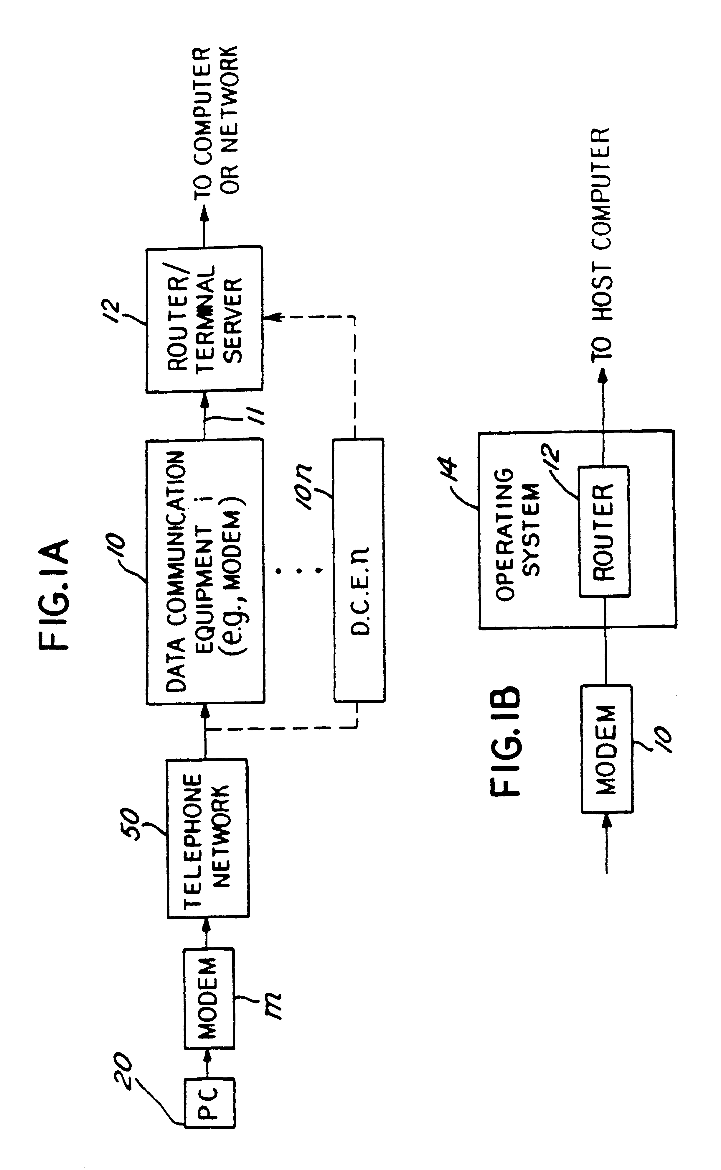
Referring to FIG. 1A, the invention may be implemented in a communications system in which a call originates from a computer, such as a PC 20, which sends data via a Data Communications Equipment (DCE) (such as modem M) onto telephone network 50 or other communications link to a receiving DCE 10, such as a modem. The call originating data terminal 20 has communication software that uses a communications protocol, such as PPP or SLIP. The DCE 10 demodulates the call from the personal computer 20 and passes it over a transmission means 11, for example an RS 232 cable or packet bus, to a router or terminal server 12. The router or terminal server 12 passes the call onto a network or host computer system for example a personal computer (not shown in FIG. 1A). Up to n DCE's 10 may be provided, depending on the amount of expected incoming traffic. Or, for some applications, only a single DCE or modem 10 may be required. The DCE 1...


PUM


Abstract

A method and apparatus for distributing protocol processing among a plurality of computing platforms. Data communications equipment such as Remote Access Devices, Communication Servers, Terminal Servers, and Dial-up Routers provide single user or large-scale multiple user communication access to various computing environments. The equipment costs and performance of such access equipment is related to the amount of CPU processing capability and memory required to support the desired number of serial communication links. It is common to use protocols that terminate in their entirely in the same processing machine. This invention encompasses methods developed to increase the cost / performance capabilities of the communication equipment that supports these serial links, primarily by means of distributing the protocol processing for higher level protocols across multiple computing platforms, including devices such as modems. Examples of such higher level protocols include PPP, SLIP and RTP.

Description

A. Field of the InventionThis invention relates to the field of data communication and apparatus and methods for receiving and transmitting data, video and / or audio communications through a communications access system, such as an integrated network access server. More particularly, the invention relates to apparatus and methods for distributing the processing of higher level network protocols for a single communication session in such a system among multiple computing platforms.Examples of such higher level network protocols which are subject to distributed processing described herein are the Point-To-Point Protocol (PPP), the Serial Line Interface Protocol (SLIP), and the Real-time Transport Protocol (RTP). However, the principles and methods of the invention are applicable to other types of higher level protocols.As described in detail below, the processing of the protocols is distributed in the preferred embodiments such that one computing platform, such as the computing platfor...

Claims


Application Information

Patent Timeline
IPC IPC(8): H04L29/06H04L29/08H04M7/00G06F13/00H04L12/64H04M3/00H04M11/00
CPCH04L12/6418H04L29/06H04L2012/6443H04L2012/6472H04L2012/6475H04L2012/6481H04L2012/6486H04M7/0006H04L69/18H04L69/12H04L69/32H04M7/0033H04M7/0051H04M7/121H04M7/1295H04L9/40
Inventor SCHOO, DANIEL L.VARMAN, RICHARDNAUDUS, STANLEY T.NADKARNI, VIJAY J.WU, YINGGENTLES, TOMTHOMPSON, LELAND O.
Owner UTSTARCOM INC
Learn More