Connector

a technology of connecting rods and locking rods, applied in the direction of connecting rods, electrical appliances, coupling devices, etc., can solve the problem of longer connector length, and achieve the effect of preventing interference of external matter with the second housing

Inactive Publication Date: 2005-06-16
SUMITOMO WIRING SYST LTD
View PDF6 Cites 7 Cited by
  • Summary
  • Abstract
  • Description
  • Claims
  • Application Information

AI Technical Summary

Benefits of technology

[0008] The rearmost end of the second housing preferably is at substantially the same position as the front end of the receptacle or inside the receptacle when the housings are connected together. Thus, interference of external matter with the second housing can be prevented.

Problems solved by technology

However, the exposure of the operable portion to the outside of the receptacle means that the entire length of the connector is longer when the housings are connected with each other.

Method used


Image

  • Connector
  • Connector
  • Connector

Examples


Embodiment Construction

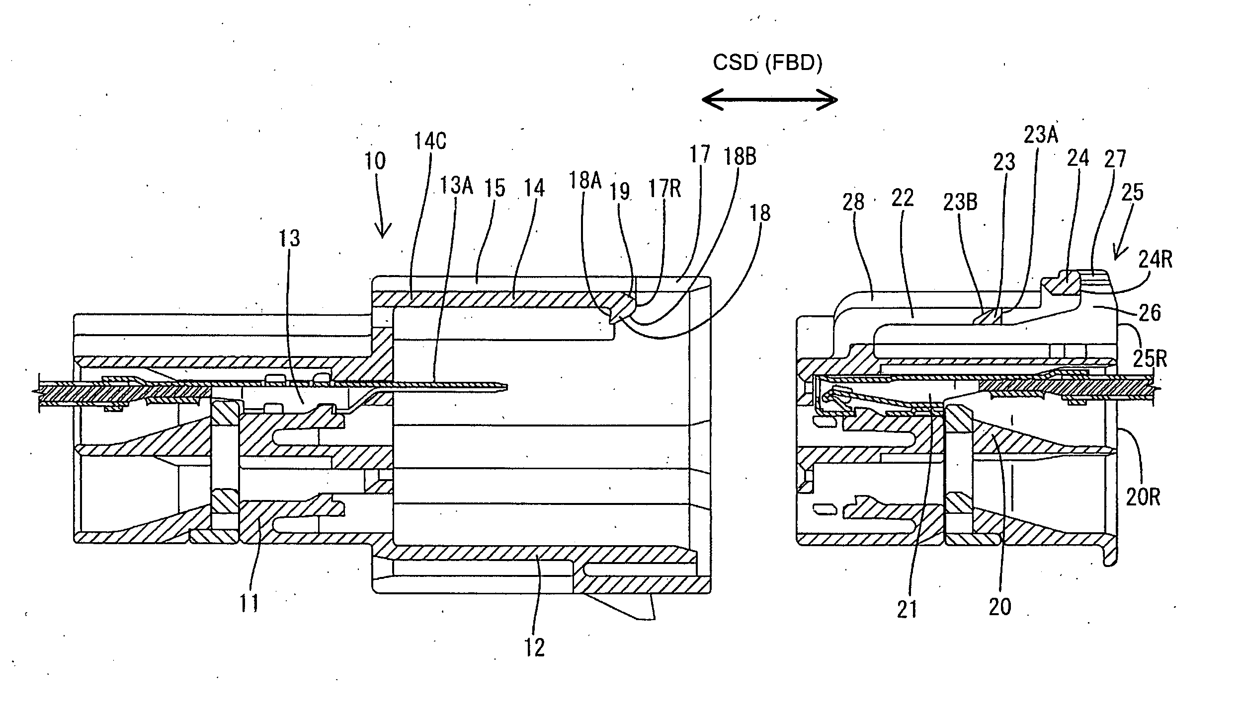
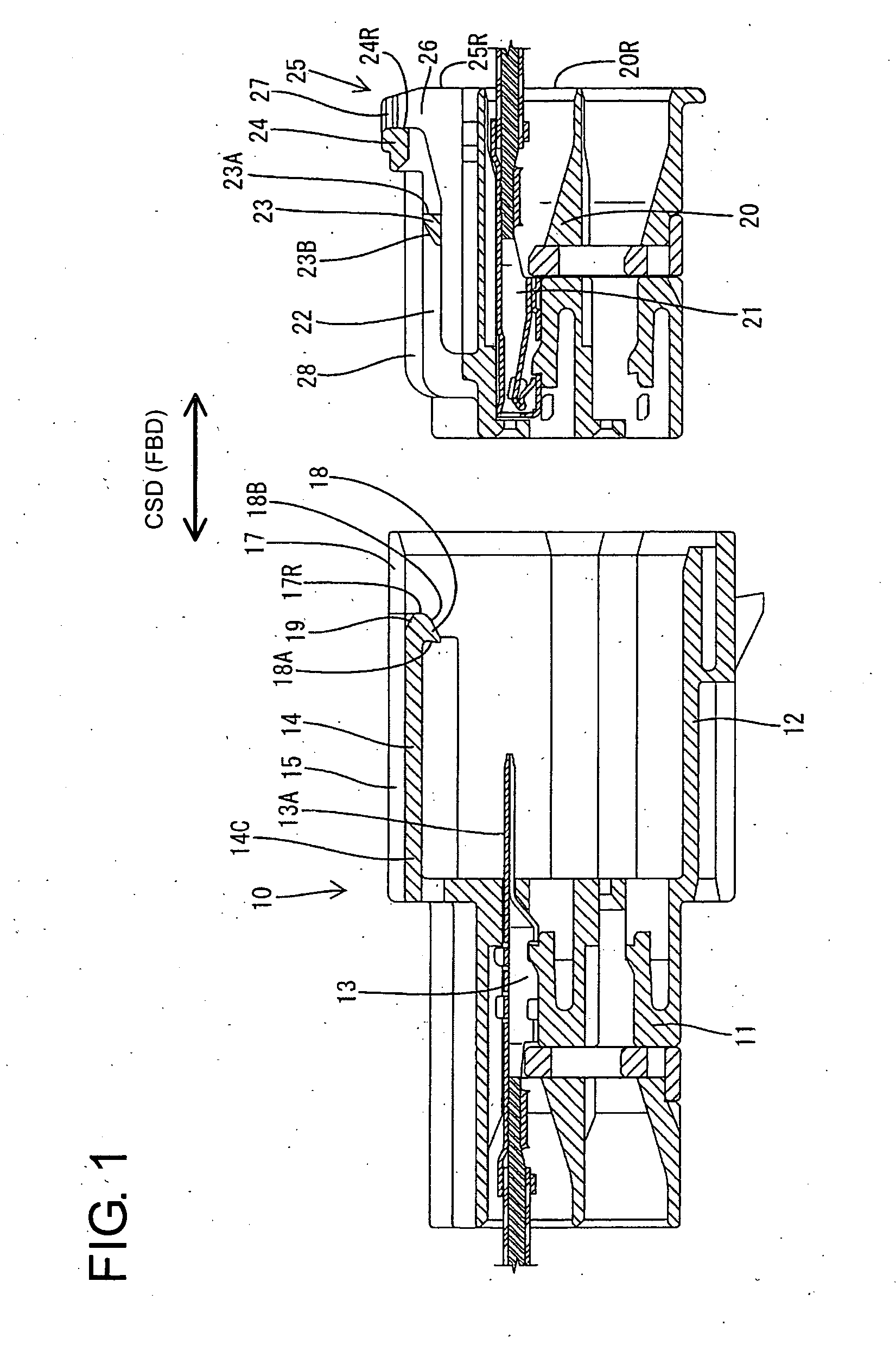
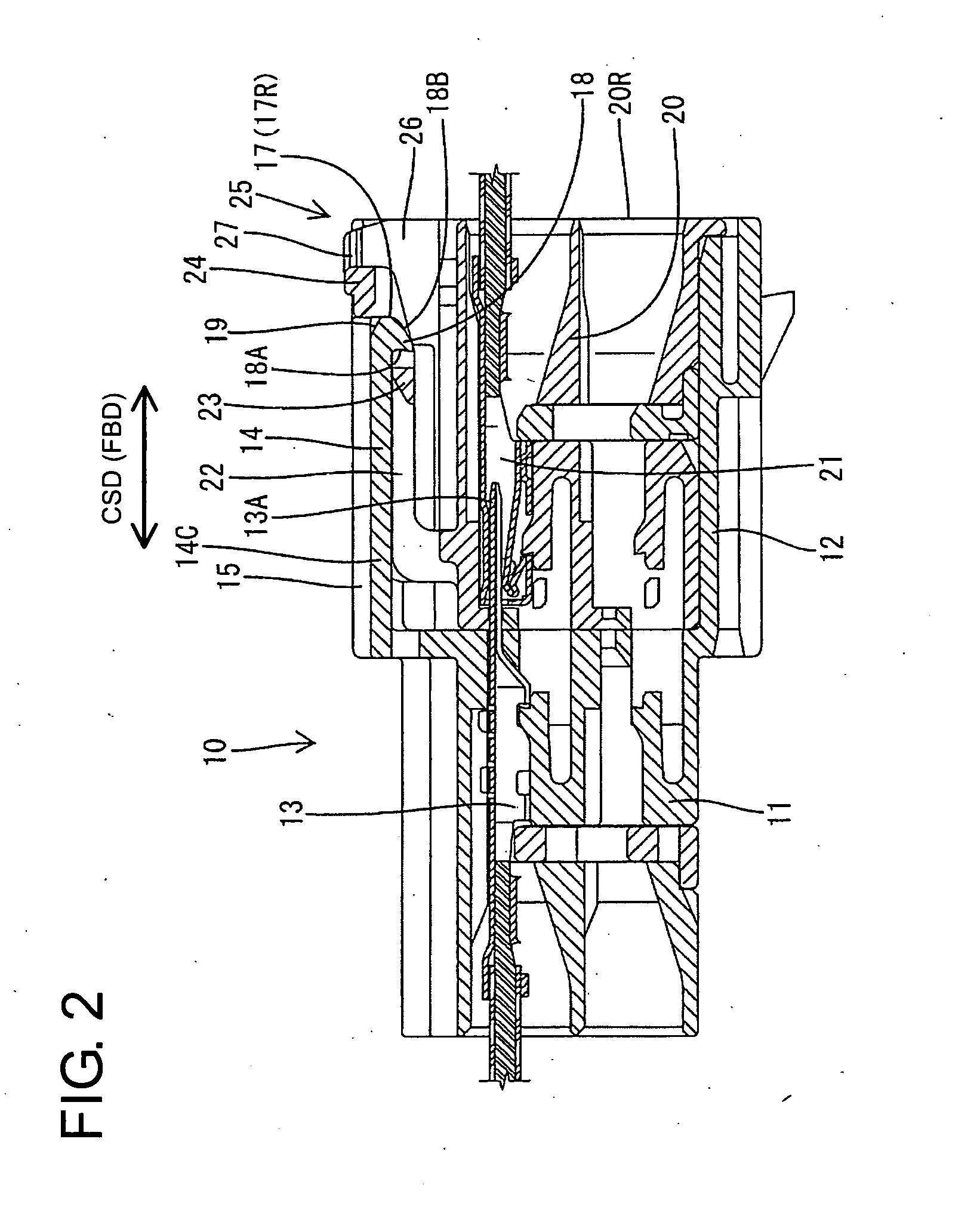
[0026] A connector according to the invention is described with reference to FIGS. 1 to 12. The connector has a male housing 10 and a female housing 20 that can be connected to abut the front surfaces thereof against each other. The housings 10, 20 also can be separated from a connected state thereof. The terms upper and lower are used herein to provide a convenient frame of reference, but are not intended to imply a required gravitational orientation.

[0027] The male housing 10 is made e.g. of a synthetic resin, and has a main body 11. A substantially rectangular transversely symmetrical receptacle 12 extends forward from the front end of the main body 11. Male terminal fittings 13 are accommodated in the main body 11, and tabs 13A at the front ends of the male terminal fittings 13 project into the receptacle 12. The receptacle 12 has an open front end and upper wall 14. Left and right narrow bulges 15 bulge out upward from the upper wall 14 and extend substantially straight along ...


PUM


Abstract

Male and female housings (10, 20) are connected and locked together by the engagement of a lock arm (22) of the female housing (20) and a lock (18) of a receptacle (12). Upon separating the two housings (10, 20), an operable portion (24) at the rear end of the lock arm (22) is operated to disengage the lock arm (22) from the lock (18), thereby canceling the locked state. Since the operable portion (24) is located in a notch (17) formed at the front end edge of the receptacle (12) with the two housings (10, 20) connected, a connector can be miniaturized with respect to a connecting direction of the two housings (10, 20).

Description

BACKGROUND OF THE INVENTION [0001] 1. Field of the Invention [0002] The invention relates to a connector with a lock arm. [0003] 2. Description of the Related Art [0004] Japanese Unexamined Patent Publication No. 2001-283979 discloses a connector that has male and female housings. The male housing has a receptacle with an open front end and the female housing fits in the receptacle to connect the housings. The female housing has a lock arm and the receptacle has a lock that is engageable with the lock arm. The lock arm engages the lock to hold the housings together. An operable portion is formed at the rear end of the lock arm and can be actuated to deform the lock arm. Thus, the lock arm disengages from the lock to cancel the locked state. [0005] The operable portion is exposed to the outside of the receptacle so that the operable portion can be pressed. However, the exposure of the operable portion to the outside of the receptacle means that the entire length of the connector is l...

Claims


Application Information

Patent Timeline
Patent Type & Authority Applications(United States)
IPC IPC(8): H01R13/639H01R13/627
CPCH01R13/6272
Inventor ISHIYAMA, TAKAYUKI
Owner SUMITOMO WIRING SYST LTD
Why Eureka
Try Eureka