Backlight Driving Board and LCD Device

a backlight driving board and liquid crystal display technology, applied in static indicating devices, instruments, optical elements, etc., can solve problems such as poor operation stability, and achieve the effect of enhancing the stability of the lcd devi

Active Publication Date: 2014-11-13
TCL CHINA STAR OPTOELECTRONICS TECH CO LTD
View PDF7 Cites 7 Cited by
  • Summary
  • Abstract
  • Description
  • Claims
  • Application Information

AI Technical Summary

Benefits of technology

[0005]The technical problem solved by the present invention is to provide a backlight driving board and an LCD device, which can reduce the signal lines between the backlight driving board and the liquid crystal driving board in order to avoid the backlight driving board from external interference because of too many signal lines, and thus be able to enhance the stability of the LCD device when operating.
[0026]The beneficial effect of the present invention is: comparing to the conventional art, the backlight driving board of the present invention controls the light emitting of the backlight sources by setting the microprocessor to generate pulse width modulation signals such that it is possible to reduce the signal lines between the backlight driving board and the liquid crystal driving board in order to avoid the backlight driving board from external interference because of too many signal lines, and thus be able to enhance the stability of the LCD device when operating.

Problems solved by technology

Therefore, the control signals of the backlight driving board of the prior art are too many, and it easily causes poor operation stability because of the external interference.

Method used


Image

  • Backlight Driving Board and LCD Device
  • Backlight Driving Board and LCD Device
  • Backlight Driving Board and LCD Device

Examples


Embodiment Construction

[0029]The following content combines with the drawings and the embodiment for describing the present invention in detail.

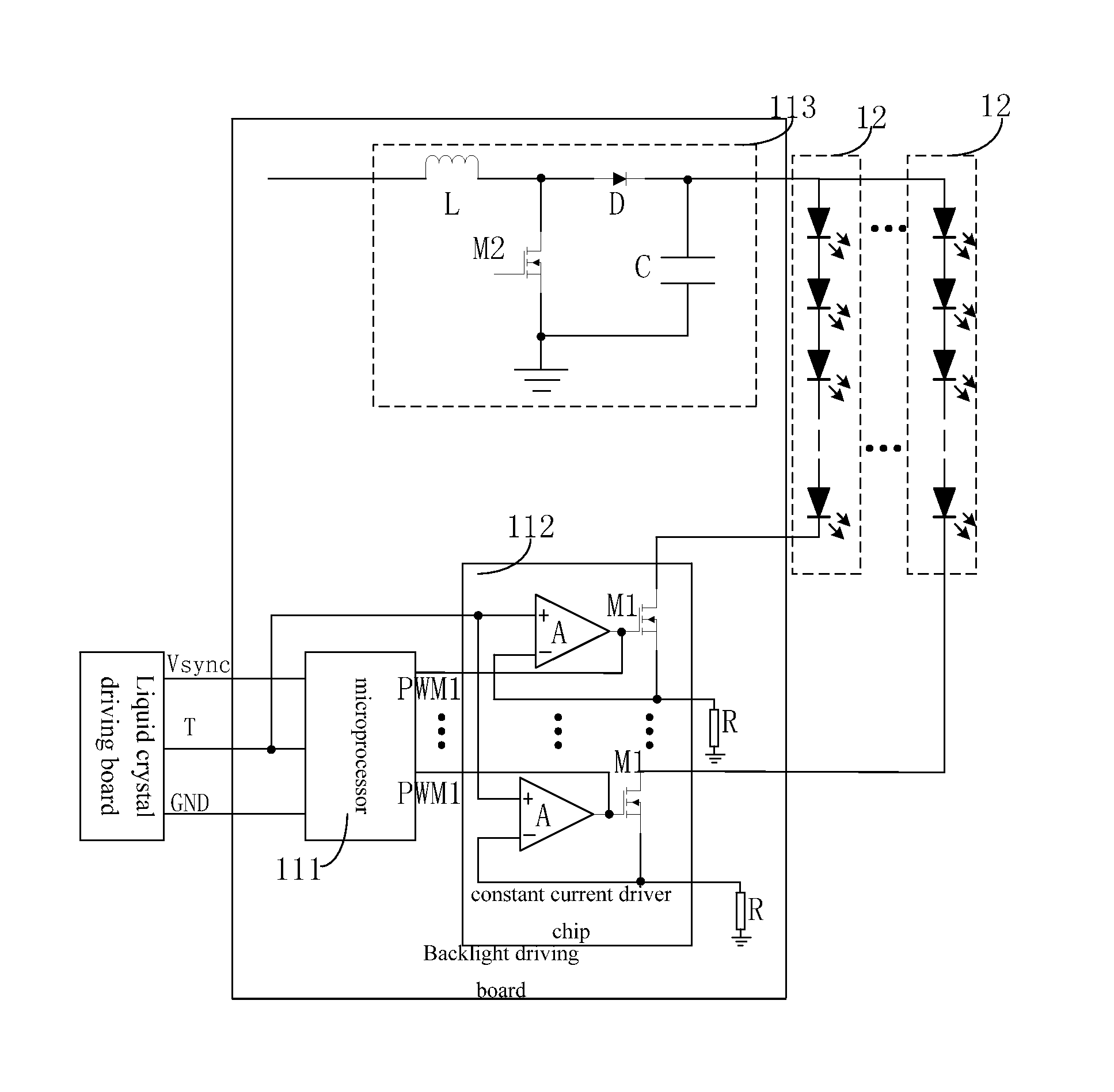
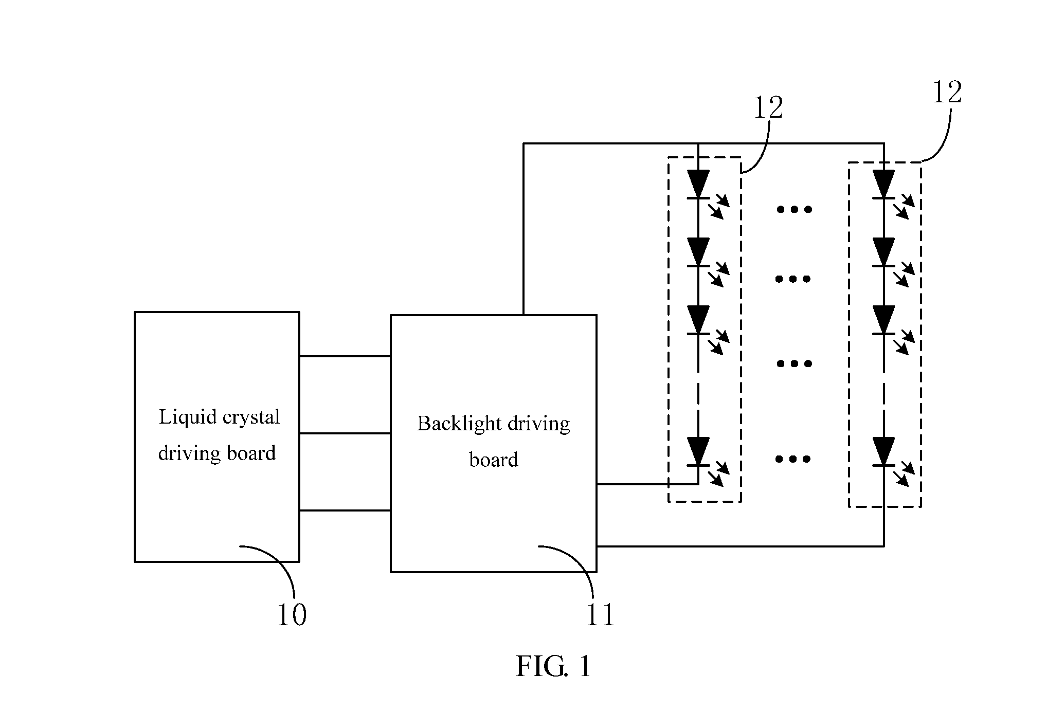
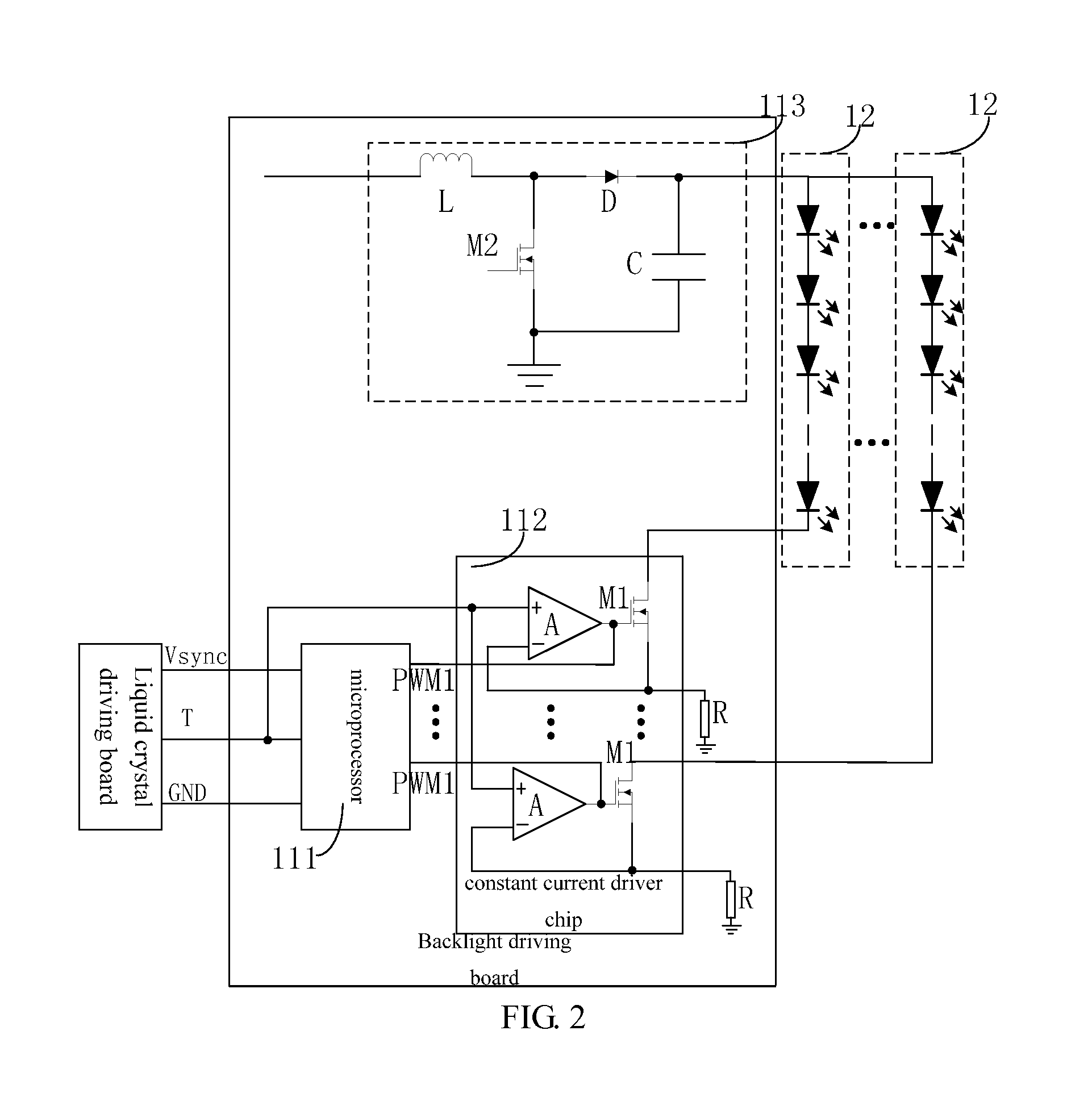
[0030]With reference to FIG. 1, FIG. 1 is a schematic block diagram of an LCD device according to an embodiment of the present invention. In the present embodiment, the LCD device preferably comprises a liquid crystal driving board 10, a backlight driving board 11 and multiple backlight sources 12. The liquid crystal driving board 10 is for controlling the deflection of the liquid crystal molecules in the liquid crystal panel (not shown) according to the display content. The backlight driving board 11 is used for controlling the light emitting of the backlight sources 12, and cooperates with the liquid crystal panel driven by the liquid crystal driving hoard 10 to complete different display effects. The LCD device require the liquid crystal driving board 10 and backlight driving board 11 to be strict synchronization in order to achieve a better display. Meanwhile,...


PUM


Abstract

The present invention discloses a backlight driving board for driving a backlight source, comprising a microprocessor and a constant current driver chip. The microprocessor receives a display mode switching signal and a synchronization signal from a liquid crystal driving board, and generating a first pulse width modulation signal corresponding to the backlight source according to the display mode switching signal and the synchronization signal. The constant current driver chip controls an operation state of the backlight source according to the first pulse width modulation signal. The present invention can reduce the signal lines between the backlight driving board and the liquid crystal driving board in order to avoid the backlight driving board from external interference because of too many signal lines, and thus be able to enhance the stability of the LCD device when operatin

Description

BACKGROUND OF THE INVENTION[0001]1. Field of the Invention[0002]The present invention relates to a liquid crystal display field, and more particularly to a backlight driving board and a liquid crystal display device including the backlight driving board.[0003]2. Description of Related Art[0004]With the development of the science and technology, the liquid crystal display (LCD) device both has the 3D and 2D display function is more popular in people's daily life. Such type of LCD device comprises a liquid crystal driving board and a backlight driving board. The liquid crystal driving board controls the backlight source to emit light. The backlight driving board and the liquid crystal driving board requires strict synchronization in order to ensure a good viewing effect. The backlight driving board of the prior art includes a constant current driver chip. The constant current diver chip receives multiple control signals from the liquid crystal driving board, and the multiple control s...

Claims


Application Information

Patent Timeline
Patent Type & Authority Applications(United States)
IPC IPC(8): G02B27/22G02F1/133G02B30/00H05B44/00
CPCG02B27/22G02F1/13306G02F2001/133626H05B45/46H05B45/20G02F1/133603G09G3/34
Inventor ZHANG, HUAZHANG, XIANMINGYANG, XIANG
Owner TCL CHINA STAR OPTOELECTRONICS TECH CO LTD
Why Eureka
Try Eureka