Lubricant draining device

a technology of lubricant and draining device, which is applied in the direction of drip or splash lubrication, machines/engines, manufacturing tools, etc., can solve the problems of affecting the safety of the environment, the floor surface on which the machine structure is placed becomes slippery, and it is generally difficult for the operator to wipe off the drained lubricant by hand work, etc., to achieve the effect of simplifying or eliminating subsequent work

Inactive Publication Date: 2005-06-23
FANUC LTD
View PDF9 Cites 13 Cited by
  • Summary
  • Abstract
  • Description
  • Claims
  • Application Information

AI Technical Summary

Benefits of technology

[0007] It is an object of the present invention to provide a lubricant draining device in which, when a lubricant supplied to the mechanical section of a machine structure is exchanged or replenished, it is possible to simplify or eliminate a subsequent work, such as a cleaning, which would normally be conducted after a lubricant exchanging operation.

Problems solved by technology

If the wiping off of the drained lubricant is omitted, several disadvantages may be caused such that an object to be handled by the machine structure, such as a workpiece or a product, is soiled by the lubricant, or that the floor surface on which the machine structure is placed becomes slippery and thereby the safety of the environment is impaired.
Indeed, various peripheral devices, jigs, wires, pipes, and so on, are often disposed around the machine structure and, therefore, it is generally difficult for the operator to wipe off the drained lubricant by hand work.

Method used


Image

  • Lubricant draining device
  • Lubricant draining device
  • Lubricant draining device

Examples


Embodiment Construction

[0033] The embodiments of the present invention are described below in detail, with reference to the accompanying drawings. In the drawings, the same or similar components are denoted by common reference numerals.

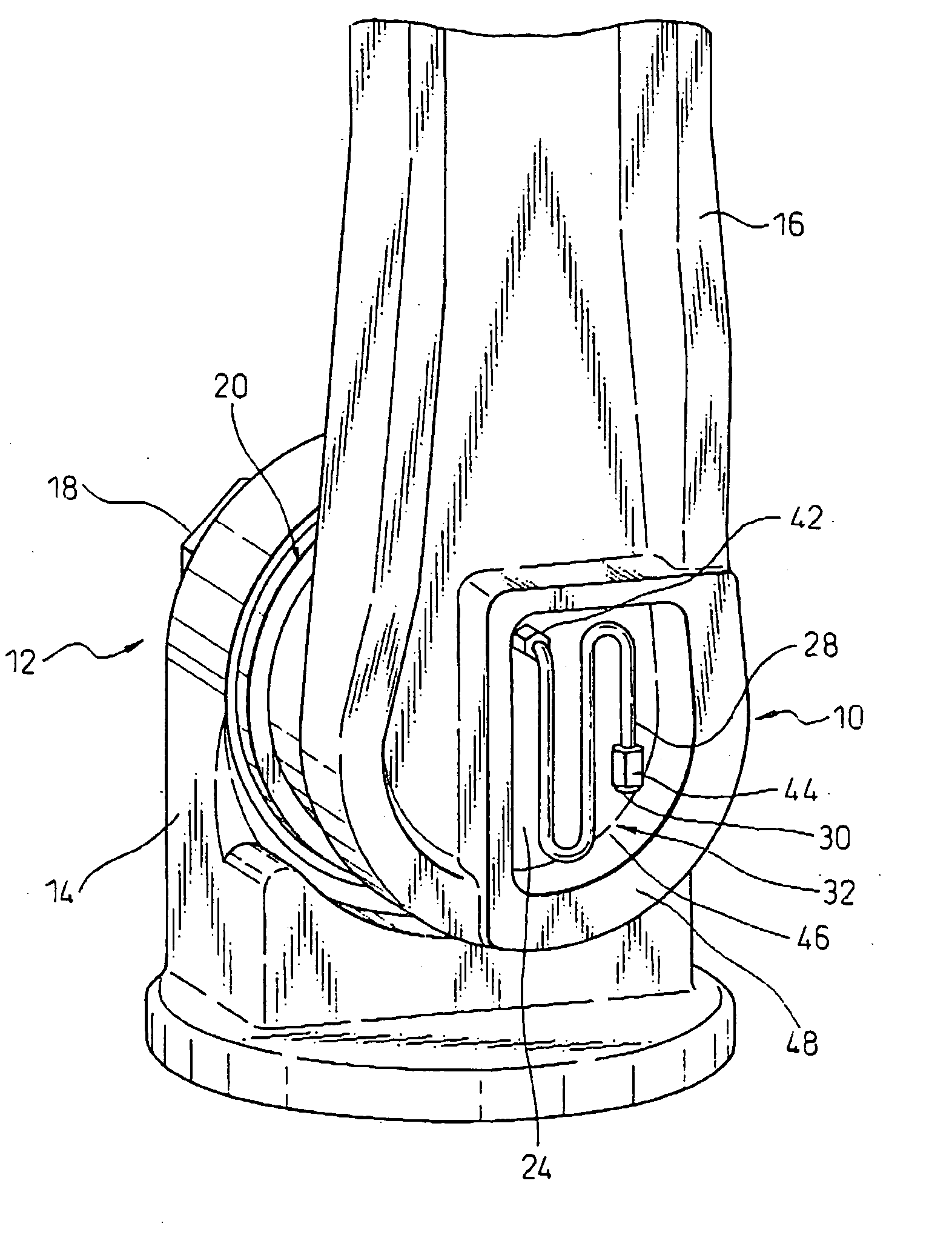
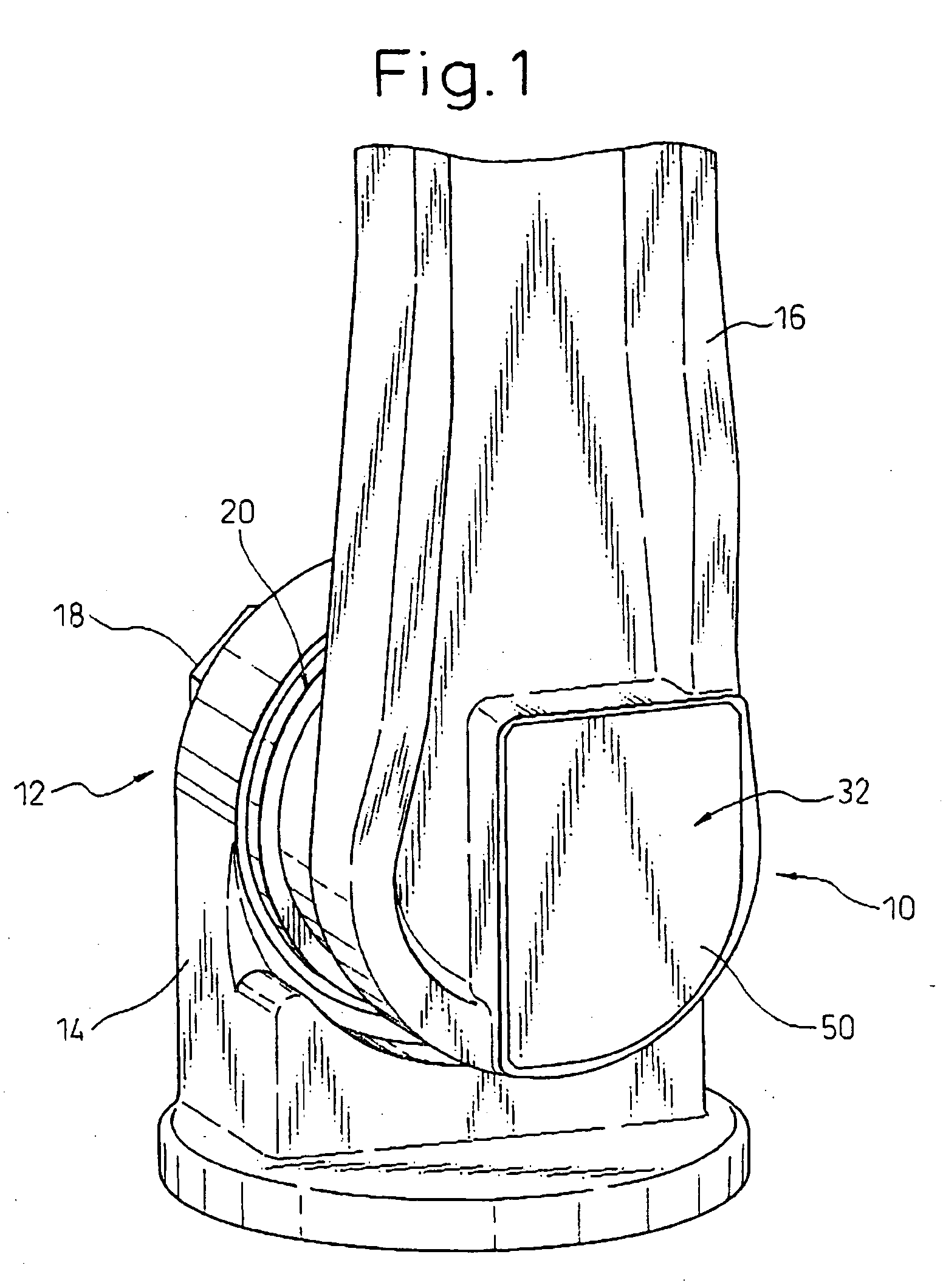
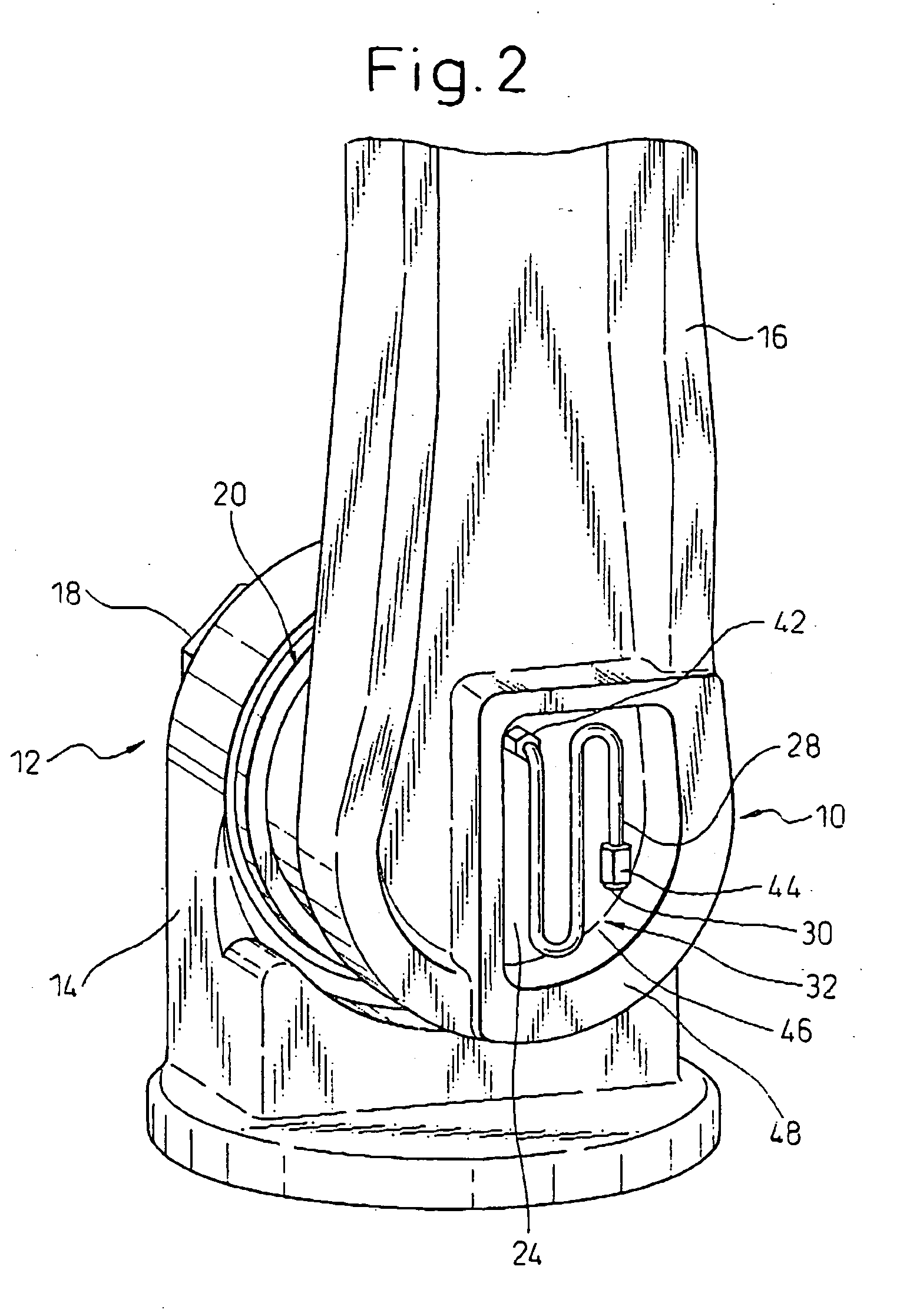
[0034] In each of the illustrated embodiments, a lubricant draining device according to the present invention is provided for a reduction mechanism incorporated in a joint section of a robot. The present invention exhibits a significant utility in various mechanical structures, especially in a robot, a machine tool and an injection molding machine, for the purpose of exchanging or replenishing a lubricant in connection with a closed mechanical section including relatively movable mechanical parts.

[0035] Referring to the drawings, FIGS. 1 to 3 respectively show a lubricant draining device 10, according to the first embodiment of the present invention, and a robot joint section 12 in which the lubricant draining device 10 is arranged.

[0036] In the robot joint section 12 as...


PUM

PropertyMeasurementUnit
flexibleaaaaaaaaaa
pressureaaaaaaaaaa
coloraaaaaaaaaa

Abstract

A lubricant draining device for draining a lubricant from a closed mechanical section provided in a machine structure such as a robot, a machine tool and an injection molding machine. The lubricant draining device includes a wall defining the mechanical section, the wall including a drain port communicated with an interior space of the mechanical section while permitting a lubricant to flow therethrough; a tube connected at a proximal end thereof to the drain port and permitting a lubricant to flow therethrough; a blocking member blocking a flow of a lubricant through the tube in a releasable manner; and a retaining section retaining the tube at a location adjacent to the wall with the tube being kept connecting with the drain port. The retaining section may include a chamber, provided on the wall, for accommodating the tube in its entirety with the tube being removable from the chamber. The chamber may be provided with a detachable cover.

Description

BACKGROUND OF THE INVENTION [0001] 1. Field of the Invention [0002] The present invention relates to a lubricant draining device. [0003] 2. Description of the Related Art [0004] In a machine structure, such as a robot, a machine tool or an injection molding machine, a mechanical section including relatively movable mechanical parts is usually supplied with a lubricant, such as grease or oil. Especially, in a mechanical section formed in a closed space, such as a reduction mechanism, a wall defining the mechanical section is provided with a pouring port for pouring a new lubricant into the interior space of the mechanical section and a drain port for draining an old degraded lubricant from the interior space of the mechanical section. [0005] In the closed mechanical section as described above, at the time when a lubricant is exchanged or replenished, a grease gun or other tool is used to pour a new lubricant into the interior space of the mechanical section through the pouring port u...

Claims


Application Information

Patent Timeline
Patent Type & Authority Applications(United States)
IPC IPC(8): B25J19/00B23Q11/12B29C45/83F16N31/00
CPCF16N31/00B25J19/0062B25J19/0066
Inventor OKADA, TAKESHIJINUSHI, MUNEHIROKUREBAYASHI, HIDENORI
Owner FANUC LTD
Why Eureka
Try Eureka