Slip clutch with different slip points for forward and reverse

a technology of forward and reverse, which is applied in the direction of friction clutches, slip couplings, clutches, etc., can solve the problem of clutch slipping at a lower torque in the forward direction

Inactive Publication Date: 2005-06-23
CNH IND AMERICA LLC
View PDF4 Cites 55 Cited by
  • Summary
  • Abstract
  • Description
  • Claims
  • Application Information

AI Technical Summary

Benefits of technology

[0009] This simple change in the shape of only two of the many parts in a clutch assembly, yields the very desirable result of allowing any apparatus protected by a slip clutch to be cleared of a blockage by merely reversing the motion of the appar

Problems solved by technology

That results in the clutch slipping at a lower torque in the forward dir

Method used


Image

  • Slip clutch with different slip points for forward and reverse
  • Slip clutch with different slip points for forward and reverse
  • Slip clutch with different slip points for forward and reverse

Examples


Embodiment Construction

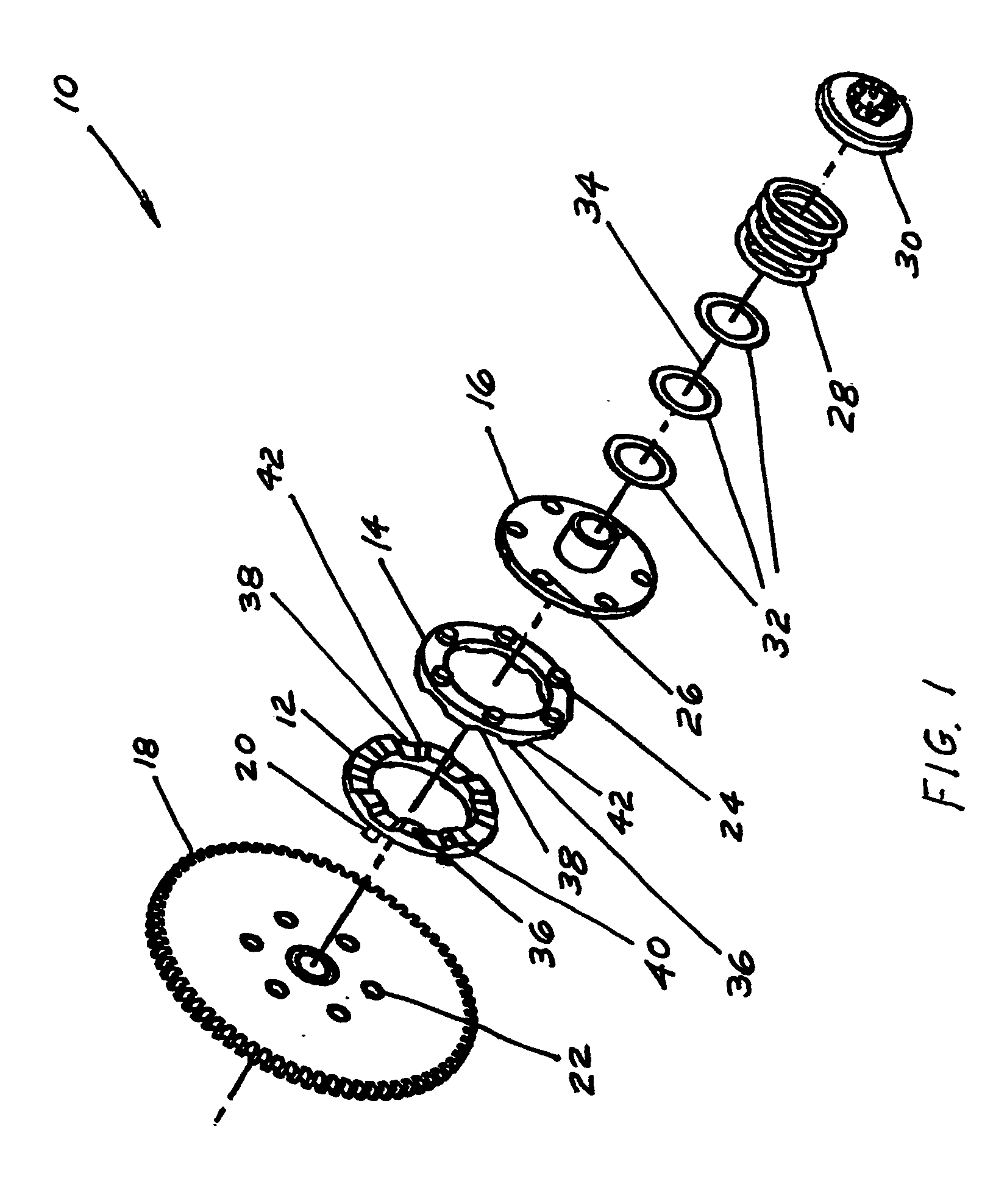
[0013]FIG. 1 is an exploded perspective view of a typical jaw slip clutch assembly 10 of the prior art. The most pertinent parts of the assembly for the purpose of the present invention are clutch jaws 12 and 14, which interlock to transfer power from drive plate 16 to driven gear 18. Driven clutch jaw 12 has rear pins 20 that lock into holes 22 on driven gear 18, and drive clutch jaw 14 has similar rear pins 24 that lock into holes 26 on drive plate 16. The other active parts of slip clutch assembly 10 are compression spring 28 and spring locking assembly 30. Drive plate 16, compression spring 28, and spring locking assembly 30, along with washers 32 are mounted on a drive shaft (not shown) that is on a common axis of rotation 34 for all the clutch parts and extends from drive plate 16 to spring locking assembly 30 and beyond where it is interconnected to a driving member such as a motor (not shown).

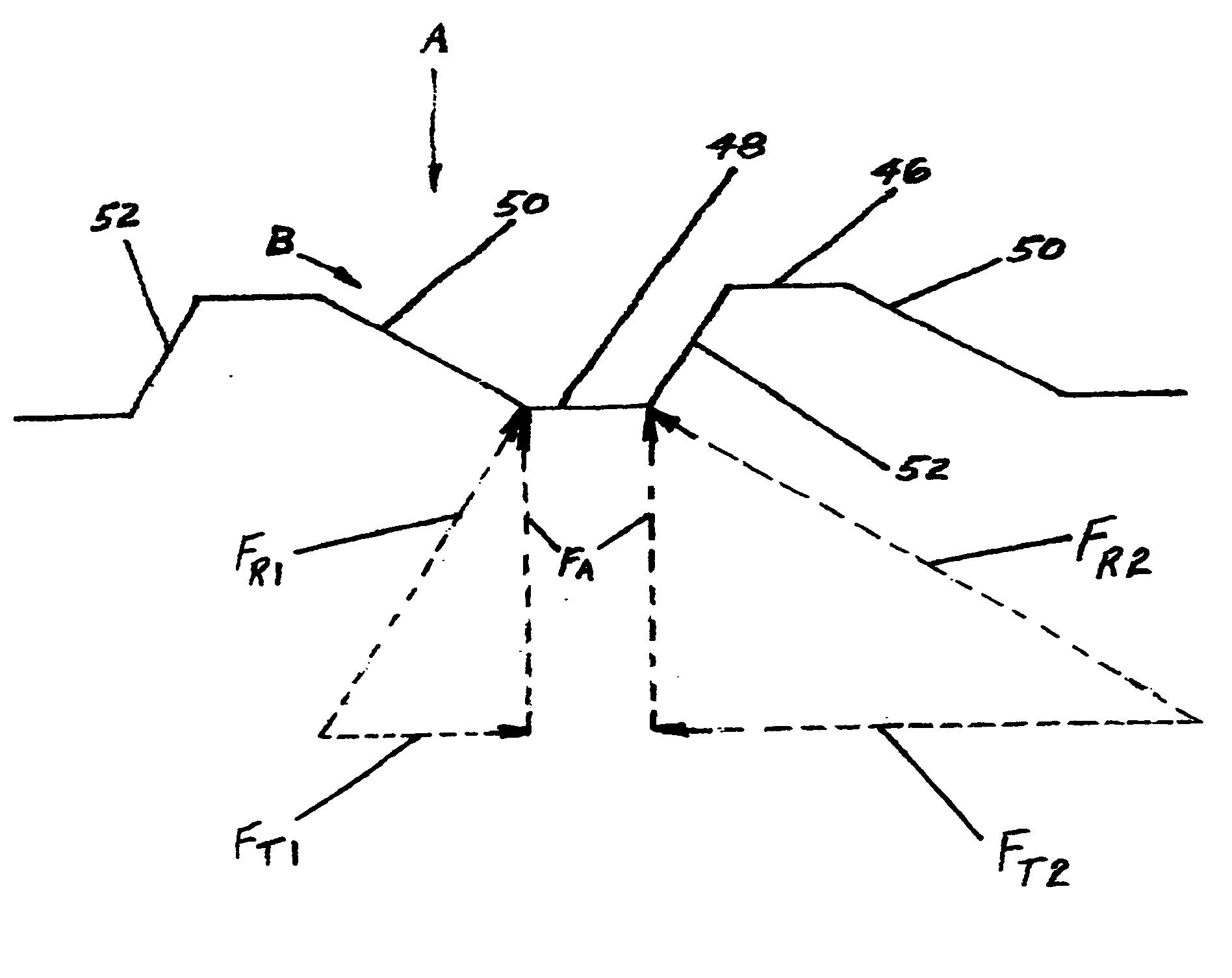
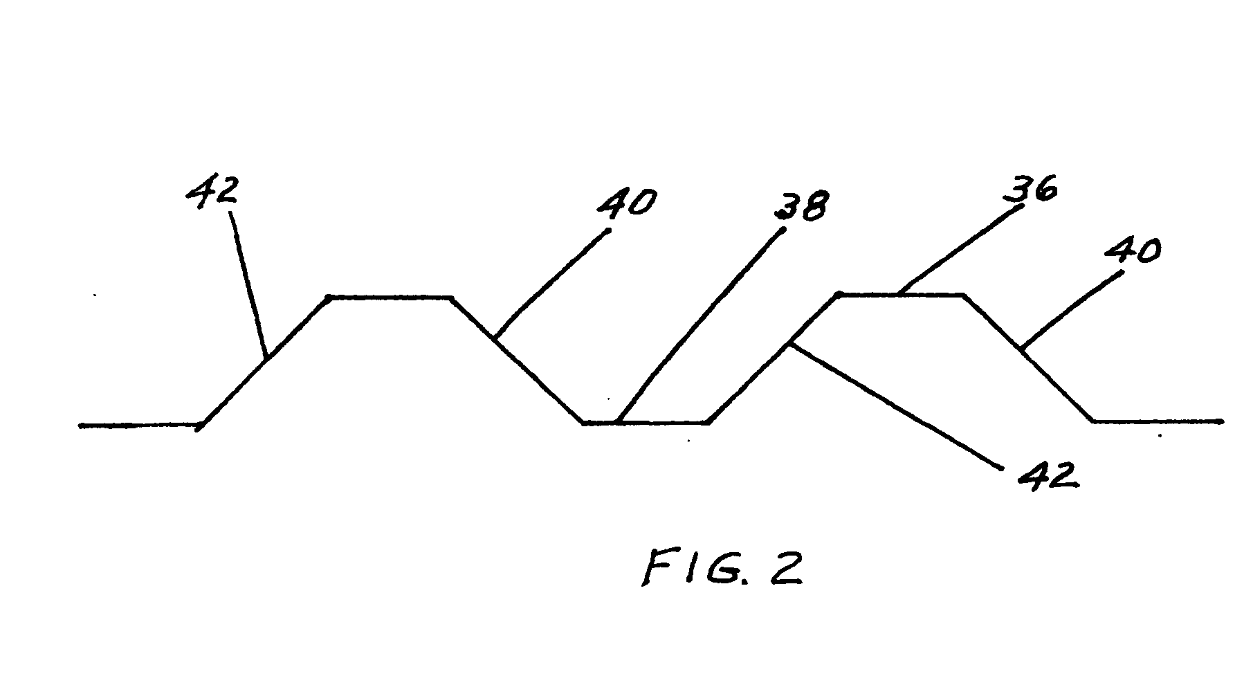
[0014] The operating function of slip clutch assembly 10 is performed by peaks 36 ...


PUM


Abstract

The apparatus is a slip clutch with matching and interlocking peaks and valleys on its two engageable surfaces and sloping sides on the peaks and valleys so that the surfaces slip on the sloping sides when the force between the surfaces exceeds the force of a spring holding the surfaces together. The slopes of the opposite sides of the peak and valleys are different so that the slip point of the clutch is different depending upon the direction of motion of the clutch.

Description

BACKGROUND OF THE INVENTION [0001] This invention deals generally with slip clutches and more specifically with a slip clutch that has higher slip torque in one direction than it has in the opposite direction. [0002] Slip clutches are relatively common devices in many applications. They serve to protect motors, transmissions, and other power transfer equipment from harmful overloads. Perhaps the most common slip clutch is one in which there is an inherent limit of the coefficient of friction between two rotating disc surfaces that are in contact with each other. In such an arrangement, when the driven surface of the clutch is stopped for any reason, the driving surface continues rotating and the two contacting surfaces simply slip on each other because the torque between them overcomes the friction between their surfaces. The principle is so basic that at some time we all have experienced a similar phenomenon when we wet our fingers to turn a page of a book. This increases the coeff...

Claims


Application Information

Patent Timeline
IPC IPC(8): F16D7/04F16D43/202
CPCF16D43/2024F16D7/044
Inventor STIEFVATER, THOMAS L.
Owner CNH IND AMERICA LLC
Why Eureka
Try Eureka