Air treatment equipment for coating production

A technology of air treatment and coating, which is applied in the direction of gas treatment, combined device, membrane technology, etc., and can solve problems such as the impact of equipment operation

Inactive Publication Date: 2021-08-17
惠州市旭丰新材料制造有限公司
View PDF0 Cites 0 Cited by
  • Summary
  • Abstract
  • Description
  • Claims
  • Application Information

AI Technical Summary

Problems solved by technology

[0002] In the production process of paint, during the air treatment process of traditional air treatment equipment, some floating molecules of paint will gradually accumulate in the entire working space of the air treatment equipment, which will affect the operation of the equipment, so a paint production method is designed Air Treatment Equipment

Method used


Image

  • Air treatment equipment for coating production
  • Air treatment equipment for coating production
  • Air treatment equipment for coating production

Examples


specific Embodiment approach 1

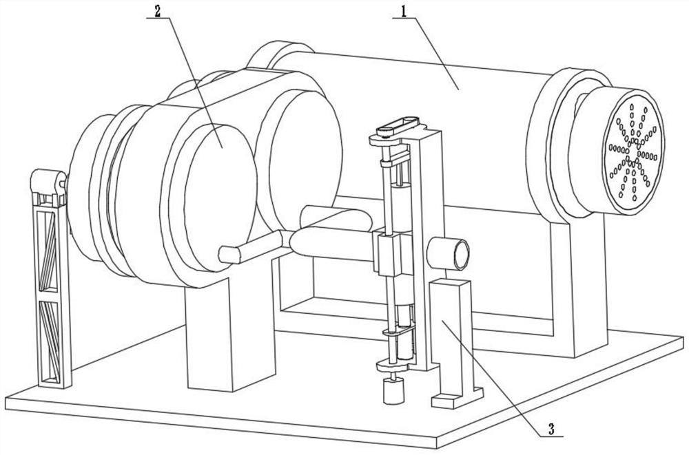
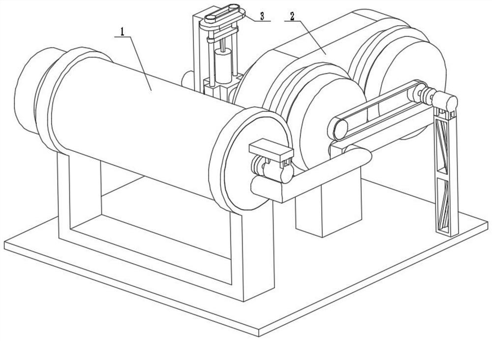
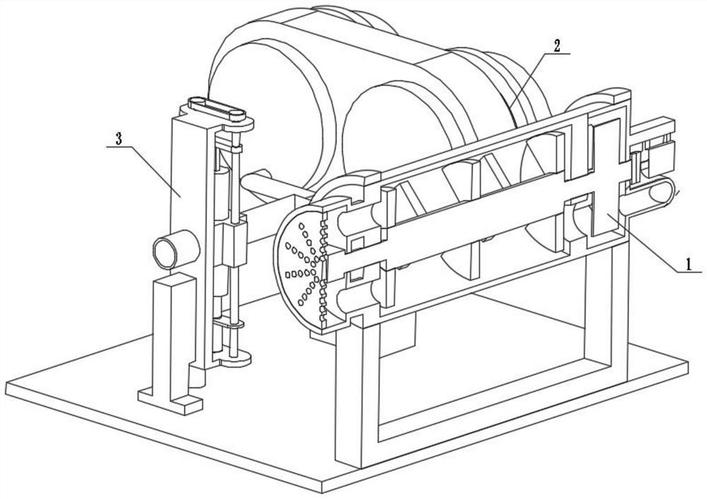
[0030] Combine below figure 1 , figure 2 , image 3 , Figure 4 , Figure 5 , Figure 6 , Figure 7 , Figure 8 , Figure 9 , Figure 10 , Figure 11 , Figure 12 , Figure 13 , Figure 14 , Figure 15 Describe this embodiment. The present invention relates to an air treatment equipment, more specifically, an air treatment equipment for paint production, including a paint molecule removal mechanism 1, an adsorption mechanism 2, and an adjustment and cleaning mechanism 3. The equipment can filter and remove floating paint. Molecules, the equipment can fully absorb the gas, the equipment can cool the gas to a certain extent, the equipment can maintain the speed of the wind, and the equipment can clear the blockage.

[0031] The paint molecule removal mechanism 1 is connected with the adsorption mechanism 2, and the adsorption mechanism 2 is connected with the adjustment and cleaning mechanism 3.

specific Embodiment approach 2

[0033] Combine below figure 1 , figure 2 , image 3 , Figure 4 , Figure 5 , Figure 6 , Figure 7 , Figure 8 , Figure 9 , Figure 10 , Figure 11 , Figure 12 , Figure 13 , Figure 14 , Figure 15 Describe this embodiment, this embodiment will further explain the first embodiment, the paint molecule removal mechanism 1 includes a filter plate 1-1, an air inlet box 1-2, a connecting pipe 1-3, an auxiliary support 1-4, and a blower 1-5, air outlet box 1-6, air outlet box I1-7, coupling 1-8, motor 1-9, connecting pipe 1-10, air outlet pipe 1-11, splitter box 1-12, air outlet pipe 1-13, rotating shaft with seat 1-14, molecular grid block 1-15, wind wheel 1-16, partition plate with connecting port 1-17, cleaning seat 1-18, sliding chamber 1-19, spring 1-20 , the sliding seat 1-21, the filter plate 1-1 is connected with the air inlet box 1-2, the air inlet box 1-2 is connected and communicated with the connecting pipe 1-3, and the connecting pipe 1-3 is connected...

specific Embodiment approach 3

[0035] Combine below figure 1 , figure 2 , image 3 , Figure 4 , Figure 5 , Figure 6 , Figure 7 , Figure 8 , Figure 9 , Figure 10 , Figure 11 , Figure 12 , Figure 13 , Figure 14 , Figure 15 Describe this embodiment, this embodiment will further explain Embodiment 1. The adsorption mechanism 2 includes a motor steel frame support base 2-1, a motor I2-2, a coupling I2-3, and a rotating wheel with a compartment 2- 4. Outer ring gear 2-5, auxiliary support seat 2-6, outer ring gear I2-7, outer box 2-8, air outlet pipe 2-9, cleaning compression pipe 2-10, threaded hole seat for collecting air outlet Pipe 2-11, pressure relief pipe 2-12, base 2-13, secondary air outlet pipe 2-14, outer box I2-15, belt shaft pulley 2-16, belt 2-17, rotating wheel with compartment I2-18, belt shaft pulley I2-19, arc protrusion 2-20, belt seat pulley 2-21, connecting column 2-22, spring 2-23, communication channel 2-24, connection port 2-25, sliding Seat I2-26, opening 2-27,...


PUM


Abstract

The invention relates to air treatment equipment, in particular to air treatment equipment forpaint production. Theair treatment equipment comprises a coating molecule removing mechanism, an adsorption mechanism and an adjusting and cleaning mechanism. The equipment can filter and remove coating floating molecules, can make gas fully adsorbed, can cool the gas to a certain degree, can keep the air outlet speed and can clean blockage; the coating molecule removing mechanism is connected with the adsorption mechanism; and the adsorption mechanism is connected with the adjusting and cleaning mechanism.

Description

technical field [0001] The invention relates to an air treatment equipment, more specifically an air treatment equipment for paint production. Background technique [0002] In the production process of paint, during the air treatment process of traditional air treatment equipment, some floating molecules of paint will gradually accumulate in the entire working space of the air treatment equipment, which will affect the operation of the equipment, so a paint production method is designed Air treatment equipment. Contents of the invention [0003] The technical problem mainly solved by the present invention is to provide a paint production air treatment equipment, the equipment can filter and remove the floating molecules of the paint, the equipment can fully absorb the gas, the equipment can cool the gas to a certain extent, and the equipment can maintain the speed of the wind , the device is able to clear the blockage. [0004] In order to solve the above technical probl...

Claims


Application Information

Patent Timeline
Patent Type & Authority Applications(China)
IPC IPC(8): B01D50/00B01D53/06
CPCB01D53/06B01D2258/06B01D50/20
Inventor 李雄飞孙业宝
Owner 惠州市旭丰新材料制造有限公司
Why Eureka
Try Eureka