Switched capacitor circuit with reduced common-mode variations

a switching capacitor and common-mode variation technology, applied in the field of electronic circuits, can solve problems such as reducing the available signal range of differential amplifiers, and achieve the effect of reducing the signal offset level and reducing the feedthrough

Active Publication Date: 2005-06-23
ANALOG DEVICES INC
View PDF6 Cites 77 Cited by
  • Summary
  • Abstract
  • Description
  • Claims
  • Application Information

AI Technical Summary

Problems solved by technology

These common-mode variations reduce the available signal range for differential amplifiers which is further reduced as circuit supply voltages are reduced.

Method used


Image

  • Switched capacitor circuit with reduced common-mode variations
  • Switched capacitor circuit with reduced common-mode variations
  • Switched capacitor circuit with reduced common-mode variations

Examples


Embodiment Construction

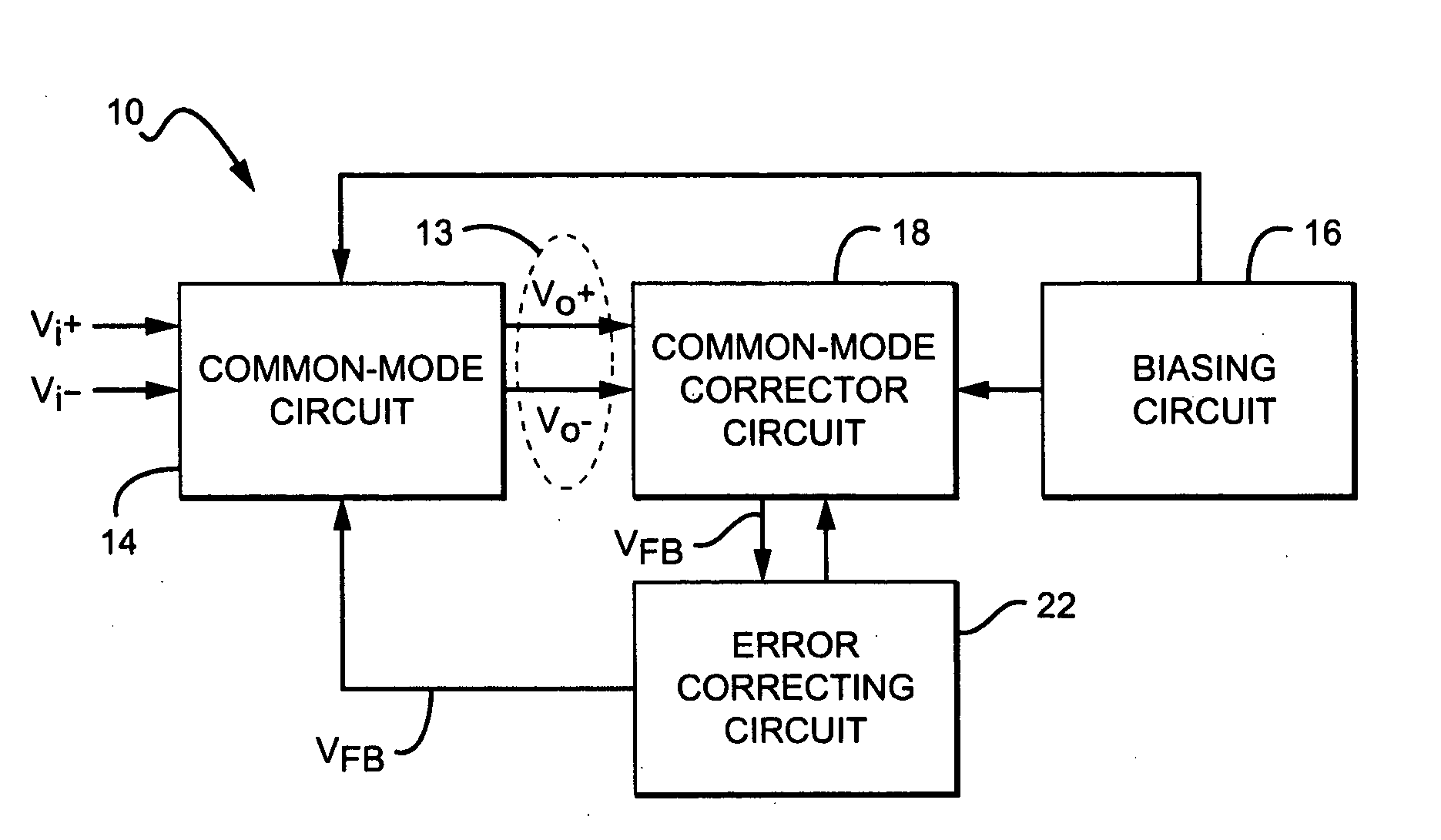
[0021]FIG. 1 illustrates a simplified block diagram of a signal conditioning system 10 in accordance with the present invention. System 10 can be included in a signal conditioning system such as an operational amplifier, an analog to digital converter, a digital to analog converter, or a similar circuit where it is desired to amplify the difference between two signals.

[0022] In one embodiment, system 10 includes a common-mode circuit 14 coupled to a common-mode corrector circuit 18 through an output port 13. Circuit 14 is also coupled to common-mode corrector circuit 18 through an error correcting circuit 22. A biasing circuit 16 is coupled to common-mode circuit 14 and common-mode corrector circuit 18 to provide power and to set an operating point for common-mode circuit 14.

[0023] Port 13 includes differential output terminals Vo+ and Vo− which provide respective differential output signals vo+ and vo− in response to differential input signals vi+ and vi− at terminals Vi+ and Vo−...


PUM


Abstract

A circuit with a common-mode dual output includes a feedback circuit connected to alternate the states of the dual output between an average output level and a desired common-mode level. The difference between the average and desired levels is proportional to a signal offset level. An impedance matching circuit is connected to the feedback circuit to adjust the signal offset level.

Description

BACKGROUND OF THE INVENTION [0001] 1. Field of the Invention [0002] This invention relates generally to electronic circuits and, more particularly, to electronic circuits which include switched capacitor circuitry. [0003] 2. Description of the Related Art [0004] For high performance signal conditioning systems, most analog circuits use dual output differential amplifiers. Differential amplifiers amplify the difference between positive and negative input signals and allow the rejection of noise from the substrate and clock signals coupled to the amplifier. However, differential amplifiers also amplify the average of the positive and negative input signals which is generally referred to as the common-mode. [0005] The common-mode limits the common-mode rejection ratio (CMRR) which is defined as the ratio of the differential mode gain to the common-mode gain. Hence, the CMRR can be increased by decreasing the common-mode gain. In differential amplifiers, the common-mode gain can be redu...

Claims


Application Information

Patent Timeline
Patent Type & Authority Applications(United States)
IPC IPC(8): H03F3/00H03F3/45
CPCH03F3/4565H03F3/005
Inventor NAIRN, DAVID G.
Owner ANALOG DEVICES INC
Why Eureka
Try Eureka