Piezoelectric transducer

a technology of piezoelectric transducers and transducers, applied in piezoelectric/electrostrictive transducers, static indicating devices, instruments, etc., can solve problems such as device charge imbalan

Inactive Publication Date: 2005-06-23
3M INNOVATIVE PROPERTIES CO
View PDF7 Cites 76 Cited by
  • Summary
  • Abstract
  • Description
  • Claims
  • Application Information

AI Technical Summary

Benefits of technology

[0007] The above summary of the present invention is not intended to describe each disclosed embodiment or every implementation of the present invention. The Figures and the detailed description that follow more particularly exemplify these embodiments.

Problems solved by technology

Mechanically stressing a piezoelectric device causes a charge imbalance in the device, setting up an electrical field that can be measured.

Method used


Image

  • Piezoelectric transducer
  • Piezoelectric transducer
  • Piezoelectric transducer

Examples


Embodiment Construction

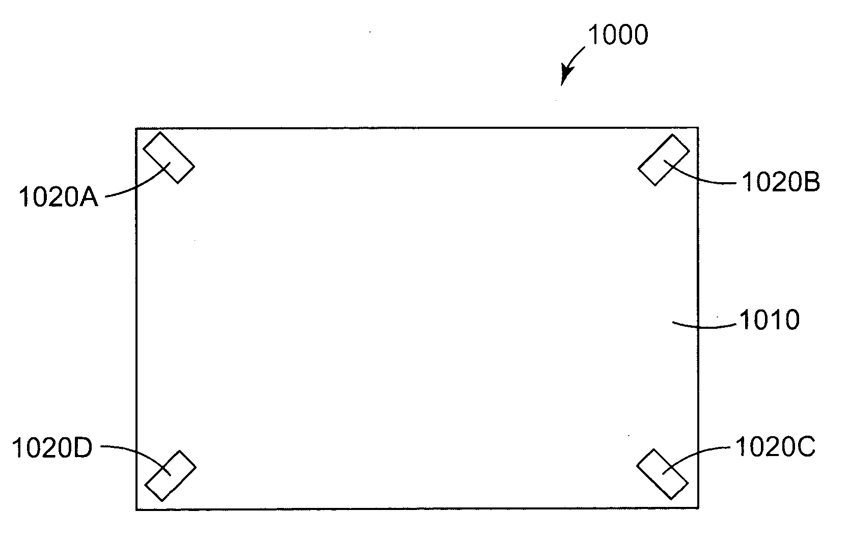
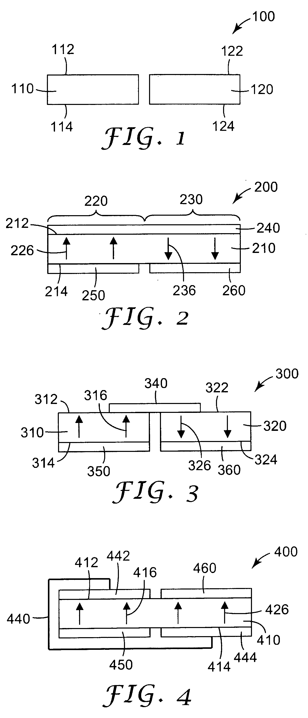
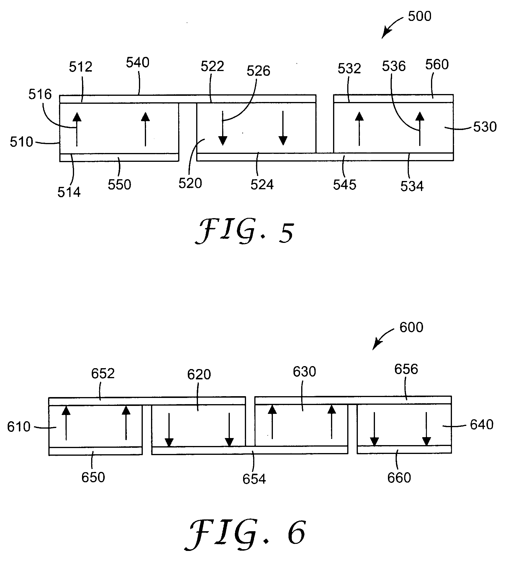
[0022] The present invention relates to piezoelectric transducers, and particularly to poled piezoelectric transducers configured for enhanced voltage sensitivity when used as vibration sensors. In the present invention, two or more poled piezoelectric devices, or two or more poled portions of the same piezoelectric device, can be arranged in a side-by-side fashion and electrically connected so that the north pole of one device (or north pole of one portion of the same device), is connected to the south pole of another device (or south pole of another portion of the same device). A side-by-side arrangement indicates that the arrangement allows the devices (or portions thereof) to be individually mechanically coupled to the same surface. This can be contrasted to a stacked arrangement of devices, for example as with so-called bi-morph piezoelectric devices. A side-by-side arrangement of devices also indicates that the devices are positioned next to each other in any direction that is...


PUM


Abstract

The present invention provides a piezoelectric transducer that includes at least two poled piezoelectric regions disposed in a side-by-side arrangement and connected in series with the poling directions reversed through the series connection, meaning that the “north pole” of one region is connected to the “south pole” of an adjacent region. The at least two regions can be within the same piece of piezoelectric material, or can be separate pieces of piezoelectric material. Transducers of the present invention may be particularly suited to detecting vibrations such as bending waves in a plate. For example, transducers of the present invention may be affixed to a surface of a plate and used to detect vibrations caused by or affected by touches to the plate to determine information related to the touches, such a touch position.

Description

[0001] This invention relates to poled piezoelectric transducers and to devices that utilize poled piezoelectric transducers for the emission or sensing of vibrations. BACKGROUND [0002] Piezoelectric devices are used to convert mechanical energy into electrical energy and electrical energy into mechanical energy. Mechanically stressing a piezoelectric device causes a charge imbalance in the device, setting up an electrical field that can be measured. Conversely, applying an electrical field across a piezoelectric device can induce a mechanical stress that can be used to controllably manipulate an object coupled to the device. In some applications, piezoelectric devices can be coupled to the surfaces of objects and used for detecting vibrations in the objects, emitting vibrations into the objects, or both. Examples of this include mechanically coupling piezoelectric devices to flat panels and using the devices to induce vibrations in the panels that lead to audible signals, thus conv...

Claims


Application Information

Patent Timeline
Patent Type & Authority Applications(United States)
IPC IPC(8): G06F3/033G06F3/041H01L41/113H01L41/22H01L41/257H04R17/00
CPCG06F3/041H04R17/00H01L41/1132H10N30/302H10N30/30
Inventor HILL, NICHOLAS P. R.
Owner 3M INNOVATIVE PROPERTIES CO
Why Eureka
Try Eureka