Ink cartridge

a technology of ink cartridges and ink cartridges, applied in the field of ink cartridges, can solve the problems of complex structure of ink flow path formation, requiring further manufacturing steps, and difficult attachment operation, so as to reduce manufacturing costs, reduce manufacturing costs, and increase the complexity of discarding ink cartridges.

Active Publication Date: 2005-06-23
BROTHER KOGYO KK
View PDF17 Cites 56 Cited by
  • Summary
  • Abstract
  • Description
  • Claims
  • Application Information

AI Technical Summary

Benefits of technology

[0013] Additionally, a compression spring made from metal is used. When recycling, a metal compression spring cannot be discarded together with the ink cartridge which is constructed from resin materials. Thus, when disposing of an ink cartridge, it is first necessary to disassemble the ink cartridge and remove the compression spring. As a result, the use of a metal compression spring entails problems in that the complexity of discarding an ink cartridge is increased, and disposal costs also become high.
[0014] The present invention allows, among other things, a reduction in manufacturing costs and a reduction in disposal costs.

Problems solved by technology

The structure for forming an ink flow path thus becomes complex.
Because the valve unit and the compression spring are attached within the ink guidance chamber, the attachment operation becomes difficult, requiring further manufacturing steps.
Consequently, high manufacturing costs are required to produce the ink cartridge.
When recycling, a metal compression spring cannot be discarded together with the ink cartridge which is constructed from resin materials.
As a result, the use of a metal compression spring entails problems in that the complexity of discarding an ink cartridge is increased, and disposal costs also become high.

Method used


Image

  • Ink cartridge
  • Ink cartridge
  • Ink cartridge

Examples


second embodiment

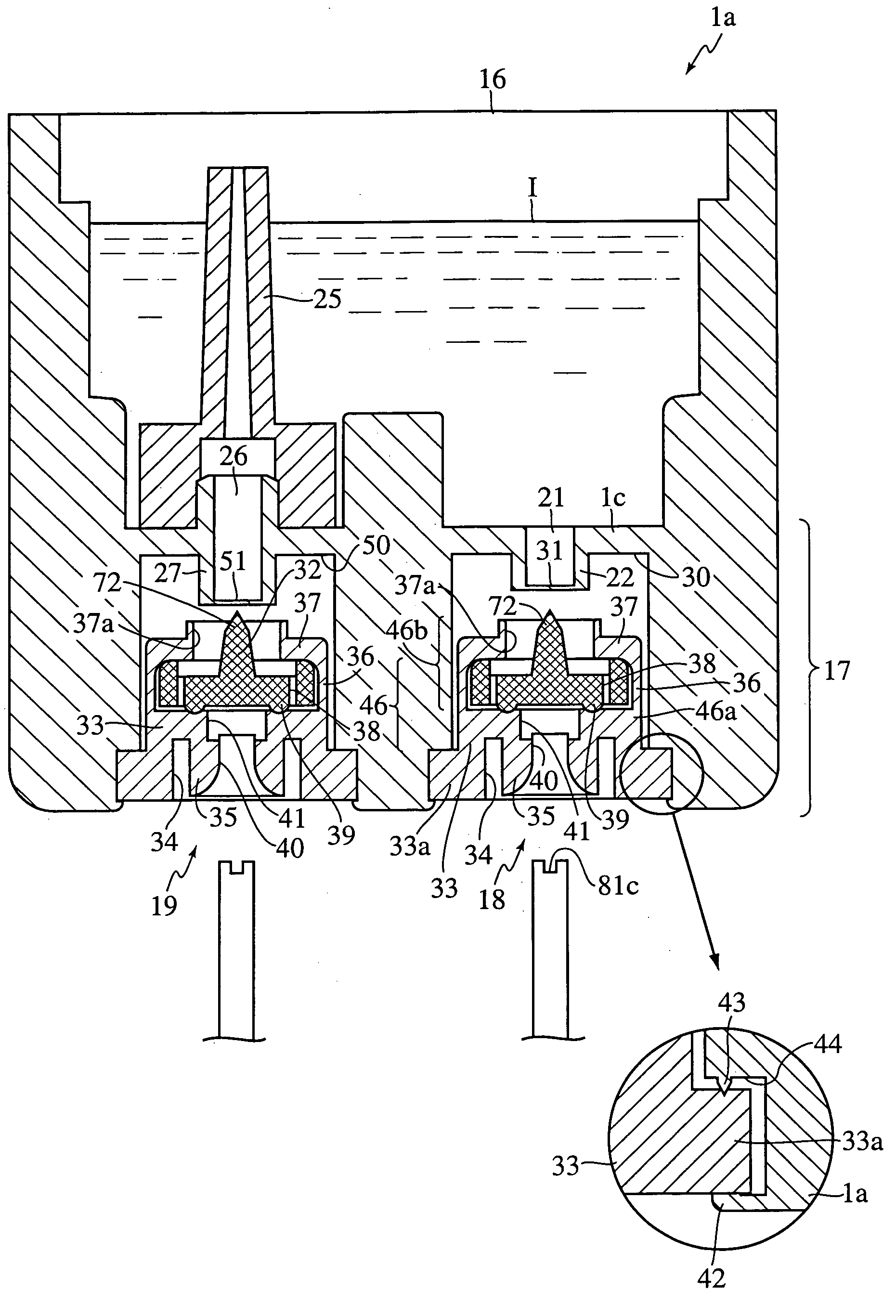
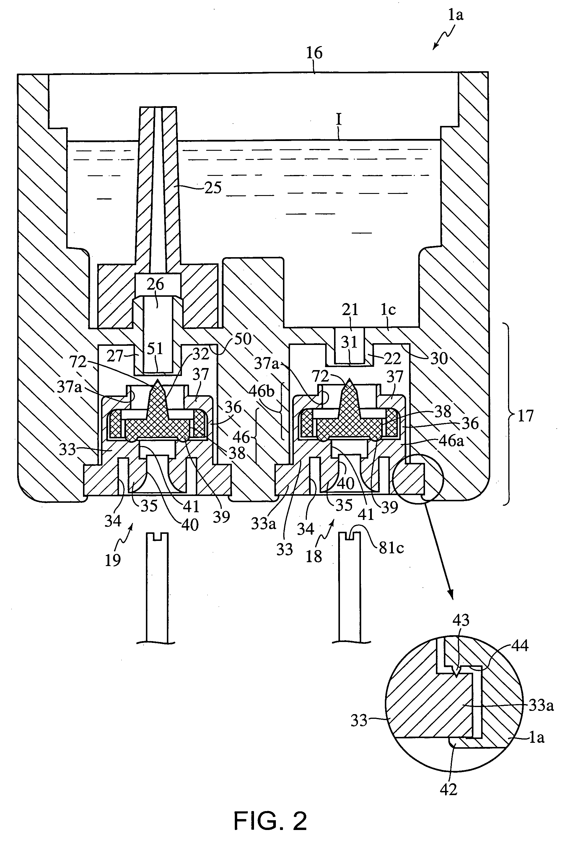
[0097] The ink cartridge 1 of the second embodiment includes the ink chamber 16 with an open top, the container wall 1a, and a cover 1f that covers the floor area 1e. The ink cartridge 1 also includes two walls 1g and 1h that form the barrel-shaped bodies 30 and 50 which are open downward. The valve device 18 is placed in the barrel-shaped body 30 and the valve device 19 is placed in the barrel-shaped body 50. The valve device 18 and the valve device 19 are identical and when they are attached to the inkjet recording device, the ink extracting tube 12 is inserted into the barrel-shaped body 30 and the air intake tube 13 is inserted into the barrel-shaped body 50.

[0098] Similar to the first embodiment, the valve device 18 and 19 have the support member 46 made of rubber-like flexible part material and the valve member 32 is made of resin. The support member 46 has basically the same structure as the support member 46 of the first embodiment, but the outer circumferential wall 33 does...

first embodiment

[0108] Unlike the first embodiment, film members 31, 51 are not used and accordingly a pointed part 72 is not used to rupture the film members 31, 51. As such, when the valve member 32 is pushed up, ink exists in the barrel shaped bodies 30, 50. However, since the circular projecting component 39 is urged against the valve seat part 46a by the projection part 37, the ink chamber 16 and the top of the barrel shaped bodies 30, 50 are reliably sealed in order to prevent ink from leaking.

[0109]FIGS. 9A and 9B show a variation of the valve member 32 shown in FIG. 8. As noted above, when the ink cartridge 1 is installed on the mounting part 3, the ink extracting tube 12 and air intake tube 13 push the valve member 32 upward, and the valve member 32 in turn pushes the projection part 37 of the urging part 46b installed in the support member 46.

[0110] On the other hand, because there are disparities in the length of the ink extracting tube 12 and the air intake tube 13, and there are also ...

third embodiment

[0125] In the third embodiment, the valve member 32 equipped with the operating member 67 is installed only in the valve device 19. However, the valve member 32 equipped with the operating member 67 may also be installed in the ink supply part so that the ink extracting tube 12 does not project to the mounting part 3.


PUM


Abstract

An ink cartridge includes an ink chamber; a communication chamber that is capable of communicating with the ink chamber; a valve that is movable; a support disposed within the communication chamber, the support including a valve seat and an opening exposing a bottom of the valve at an approximately central portion, wherein the valve seat is adjacent to the valve at an outer periphery of the opening; and an urging device that extends from the valve seat, the urging device directly contacting the valve and urging the valve toward the valve seat, wherein the valve separates from the valve seat when a predetermined force is applied to the valve and the support and the urging device are formed as a one-piece member.

Description

INCORPORATION BY REFERENCE [0001] This application claims priority from Japanese Patent Application No. 2003-394324, filed Nov. 25, 2003, Japanese Patent Application No. 2003-394323, filed Nov. 25, 2003, Japanese Patent Application No. 2003-409077, filed Dec. 8, 2003, Japanese Patent Application No. 2003-409640, filed Dec. 8, 2003, Japanese Patent Application No. 2004-031712, filed Feb. 9, 2004, Japanese Patent Application No. 2004-032872, filed Feb. 10, 2004, Japanese Patent Application No. 2004-043978, filed Feb. 20, 2004, Japanese Patent Application No. 2004-047768, filed Feb. 24, 2004, Japanese Patent Application No. 2004-053164, filed Feb. 27, 2004, and Japanese Patent Application No. 2004-060456, filed Mar. 4, 2004, the subject matter of those applications is incorporated herein by reference in its entirety. BACKGROUND OF THE INVENTION [0002] 1. Field of Invention [0003] This invention relates to an ink cartridge and an inkjet recording apparatus equipped with the ink cartridg...

Claims


Application Information

Patent Timeline
Patent Type & Authority Applications(United States)
IPC IPC(8): B41J2/175
CPCB41J2/17513B41J2/17523B41J2/17596B41J2/17556B41J2/17553B41J2/17503
Inventor SASAKI, TOYONORIHATTORI, SHINGOKANBE, TOMOHIROTAKAGI, ATSUHIRO
Owner BROTHER KOGYO KK
Why Eureka
Try Eureka