Method for sputtering magnetic recording media

Inactive Publication Date: 2005-06-23
SEAGATE TECH LLC
View PDF12 Cites 8 Cited by
  • Summary
  • Abstract
  • Description
  • Claims
  • Application Information

AI Technical Summary

Benefits of technology

[0009] In one embodiment, the present invention generally provides a method for depositing material on a substrate by disposing the substrate on a support member, sputtering material from a cathode positioned in substantially facing relationship with respect to a surface of the

Problems solved by technology

The art is deficient while providing adequate processes and apparatuses to deposit tilted perpendicular media.

Method used


Image

  • Method for sputtering magnetic recording media
  • Method for sputtering magnetic recording media
  • Method for sputtering magnetic recording media

Examples


Embodiment Construction

[0029] So that the manner in which the above recited features of the present invention can be understood in detail, a more particular description of the invention, briefly summarized above, may be had by reference to embodiments, some of which are illustrated in the appended drawings. It is to be noted, however, that the appended drawings illustrate only typical embodiments of this invention and are therefore not to be considered limiting of its scope, for the invention may admit to other equally effective embodiments.

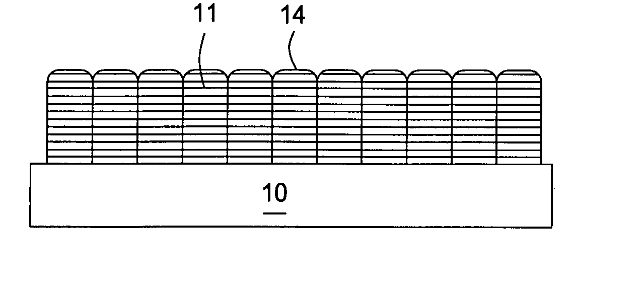
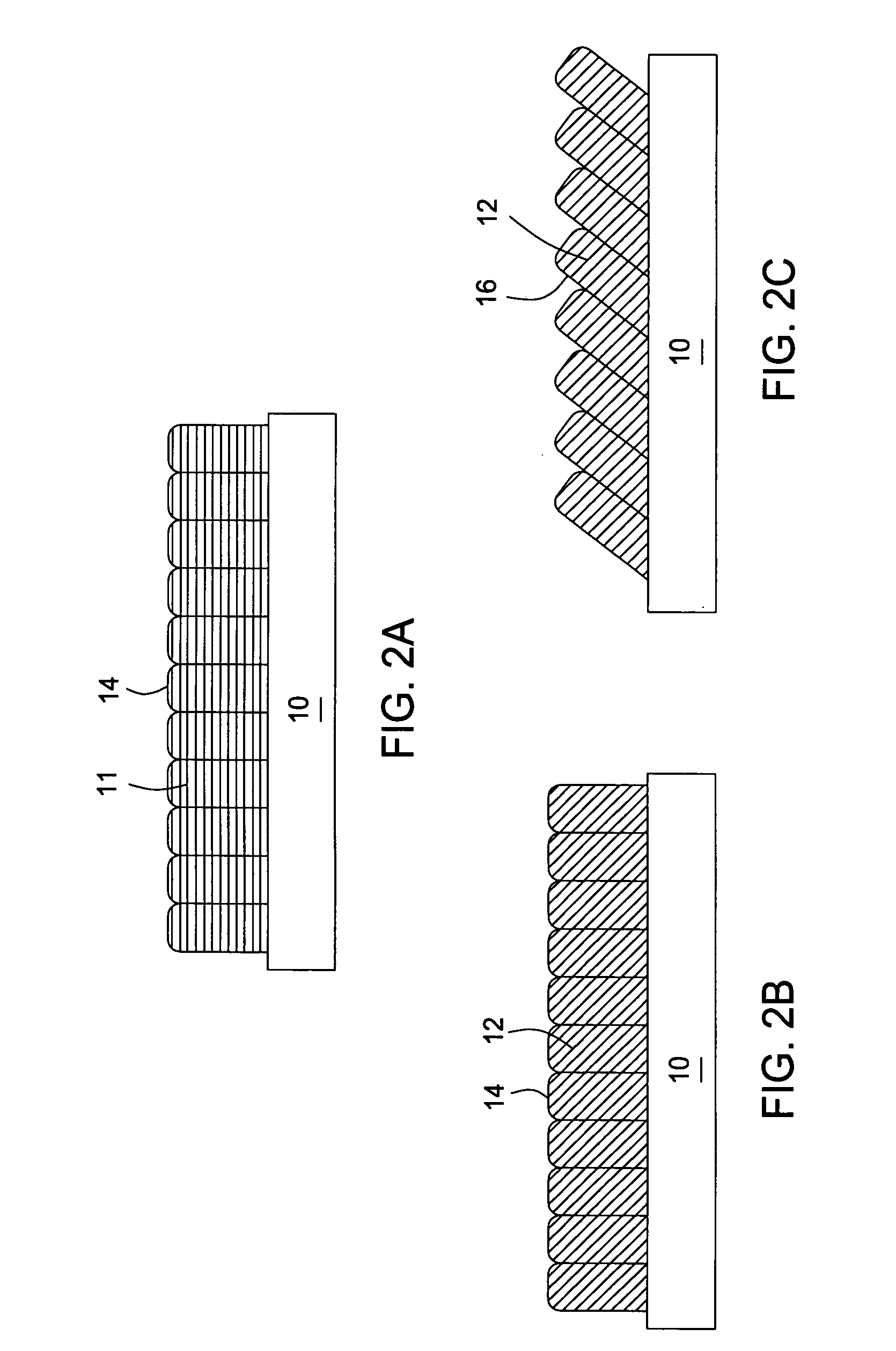
[0030] Generally, methods and apparatus are disclosed for fabrication of angle-of-incidence layers on a disk. In one embodiment, the angle-of-incidence layers may have radial and / or circumferential tilt symmetry. Deposition techniques for forming the layers on the disk include, for example, sputtering or evaporation techniques capable of producing directional material according to the desired tilt symmetry. The methods are considered capable of providing adequate unif...


PUM

PropertyMeasurementUnit
Angleaaaaaaaaaa
Angleaaaaaaaaaa
Thicknessaaaaaaaaaa

Abstract

Generally, methods and apparatus are disclosed for fabrication of angle-of-incidence layers on a substrate. In one embodiment, the angle-of-incidence layers may have either radial or circumferential tilt symmetry, using, for example, sputtering or evaporation techniques. In one example, an apparatus for sputtering material comprises a substrate support member, a cathode positioned in substantially facing relationship with respect to the substrate support member and a shutter plate. The shutter plate is disposed between the substrate support member and the cathode and defining an aperture for selective transmission of sputtered articles from the cathode on the basis of a non-perpendicular trajectory angle relative to a plane of the substrate support member.

Description

FIELD OF THE INVENTION [0001] Embodiments of the invention generally relate to apparatus and methods for directional deposition of material on magnetic recording media and more specifically, for deposition of tilt perpendicular media. BACKGROUND OF THE INVENTION [0002] Magnetic and magneto-optical media are extensively employed in the computer industry and can be locally magnetized by a write transducer or write head to record and store information. The write transducer creates a concentrated magnetic field which is directionally alternated based upon specific bits of the information being stored. When the local magnetic field produced by the write transducer is greater than the coercivity of the recording medium, grains of the recording medium at that location are magnetized. The grains retain their magnetization after the magnetic field produced by the write transducer is removed. The direction of the magnetization matches the direction of the applied magnetic field. The magnetiza...

Claims


Application Information

Patent Timeline
IPC IPC(8): B05D1/12B05D5/12C23C14/04C23C14/14C23C14/22G11B5/64G11B5/73
CPCC23C14/044C23C14/14G11B5/7325G11B5/64G11B5/656C23C14/225G11B5/7377G11B5/737G11B5/658
Inventor BRUCKER, CHARLES FREDRICKLEE, JEAN LING
Owner SEAGATE TECH LLC
Why Eureka
Try Eureka