Method and apparatus for dynamic server client controlled connectivity logic

a dynamic server client and connectivity logic technology, applied in the field of method and apparatus for dynamic server client controlled connectivity logic, can solve the problems of loss of connection, excessive power consumption, and extensive battery consumption of mobile clients, and achieve a high load for at least the access network

Inactive Publication Date: 2013-09-19
NOKIA TECHNOLOGLES OY
View PDF43 Cites 48 Cited by
  • Summary
  • Abstract
  • Description
  • Claims
  • Application Information

AI Technical Summary

Benefits of technology

[0013]In accordance with another embodiment, there is a method comprising determining a maximum packet size for which transmission will not trigger a state change for a user equipment; and restricting transmissions of background data to or from the user equipment so as not to exceed the maximum packet size.
[0014]In accordance with yet another embodiment, there is an apparatus comprising: at least one processor; and at least one memory including computer program code, where the at least one memory and the computer program code are configured, with the at least one processor, to cause the apparatus to at least: determine a maximum packet size for which transmission will not trigger a state change for a user equipment; and restrict transmissions of background data to or from the user equipment so as not to exceed the maximum packet size.

Problems solved by technology

Inadequate keep-alive timer values can lead to the loss of connections or when sent too often, into excessive power consumption.
Particularly in the developing countries there are congested cellular access networks where attempting to use always on connection during the busy hours yields to periodic loss of connection and reconnection or very frequent keep-alive packets both causing extensive battery consumption for mobile clients and a high load for at least the access network.
It can be seen that these types of transmission / reception requirements can also lead to excessive use of resources and power consumption.

Method used


Image

  • Method and apparatus for dynamic server client controlled connectivity logic
  • Method and apparatus for dynamic server client controlled connectivity logic
  • Method and apparatus for dynamic server client controlled connectivity logic

Examples


Embodiment Construction

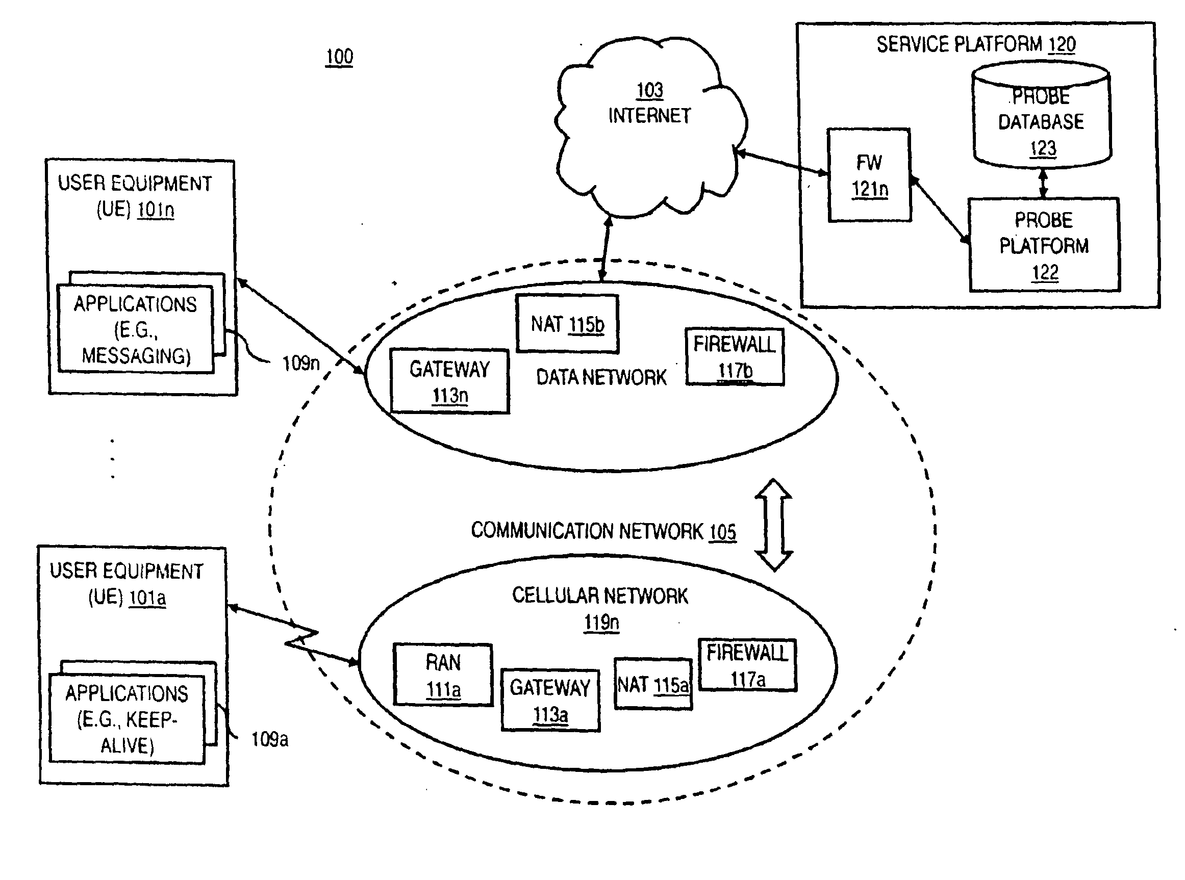
[0028]A method, apparatus, and software for probe service providing optimal keep-alive timer values, dynamically extended reconnection delays or recommendation of voluntary disconnection instead of keeping the connection alive with the said keep-alive packets, or a combination thereof are disclosed. In the following description, for the purposes of explanation, numerous specific details are set forth in order to provide a thorough understanding of the embodiments of the invention. It is apparent, however, to one skilled in the art that the embodiments of the invention may be practiced without these specific details or with an equivalent arrangement. In other instances, well-known structures and devices are shown in block diagram form in order to avoid unnecessarily obscuring the embodiments of the invention.

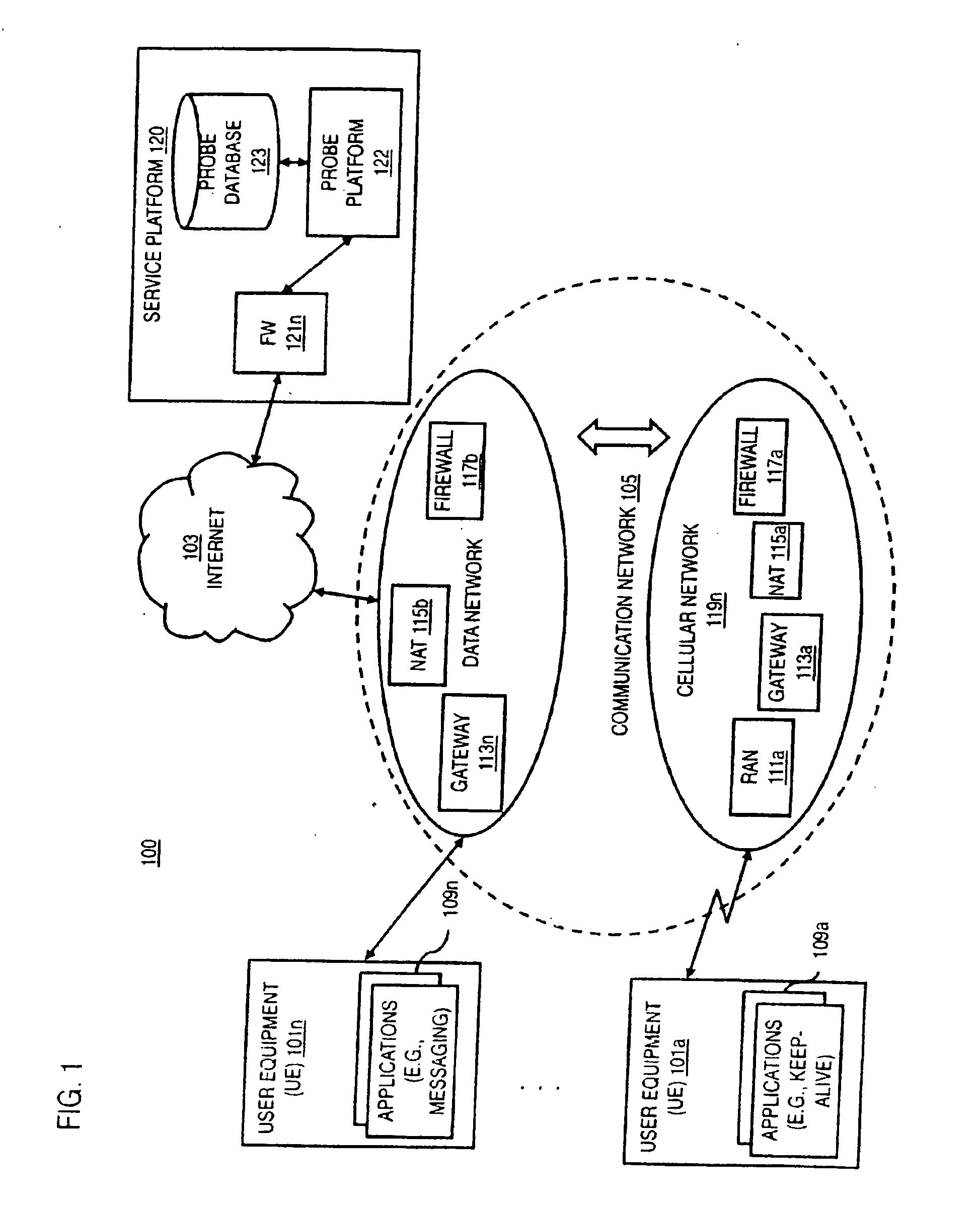
[0029]FIG. 1 is a diagram of a system capable of transmitting optimal keep-alive timer values, dynamically extended reconnection delays or recommendation of voluntary disconnecti...


PUM


Abstract

The exemplary embodiments of the invention provide at least a method and apparatus to receive a connection instruction request from a user equipment; identify a network from which the request was sent; select stored probe values and associated network information that are associated with the identified network; determine connection instructions based at least in part on the stored probe values and the associated network information, in which the connection instructions include a dynamically extended reconnection delay if a determined keep-alive timer for keep-alive instructions would be impractically short; and send the connection instructions to the user equipment. Further, the exemplary embodiments of the invention provide at least a method and apparatus to determine a maximum packet size for which transmission will not trigger a state change for user equipment; and restrict transmissions of background data to or from the user equipment so as not to exceed the maximum packet size.

Description

CROSS-REFERENCE TO RELATED APPLICATIONS[0001]This patent application claims priority under 35 U.S.C. §119(e) from U.S. Provisional Patent Application No. 61 / 602,861 filed Feb. 24, 2012, the disclosure of which is incorporated by reference herein in its entirety.TECHNICAL FIELD[0002]The teachings in accordance with the exemplary embodiments of this invention relate generally to at least determining connection instructions based at least in part on the stored probe values and the associated network information, and to determining a maximum packet size for which transmission will not trigger a state change for a user equipment and restricting transmissions of background data so as not to exceed the maximum packet size.BACKGROUND[0003]Service providers and device manufacturers are continually challenged to deliver value and convenience to consumers by, for example, providing compelling network services. Important differentiators in the industry are application and network services as we...

Claims


Application Information

Patent Timeline
Patent Type & Authority Applications(United States)
IPC IPC(8): H04L12/70
CPCH04L67/142H04W76/045H04L47/10H04W76/25
Inventor VIMPARI, MARKKUALA-KONTIOLA, JUKKA S.LI, ZEXIANVEIKKOLAINEN, SIMO P.
Owner NOKIA TECHNOLOGLES OY
Why Eureka
Try Eureka