Coaxial electrical connector

Inactive Publication Date: 2005-06-23
HIROSE ELECTRIC GROUP
View PDF8 Cites 10 Cited by
  • Summary
  • Abstract
  • Description
  • Claims
  • Application Information

AI Technical Summary

Benefits of technology

[0020] Furthermore, in this invention, the cover section can have a restricting section on the inner surface, which restricts the sliding off of the tongue in the width direction when the cover section is bent and the tongue slides over the inner surface of the cover section in the extending direction of the tongue. With those features, the tongue can stay in the intended position without sliding off in the width direction of the tongue when it is bent.
[0021] As described above, in the present invention, the receiving section to place at least a part of the tongue of the dielectric is formed, or the restricting section to restrict the movement of the tongue in the width direction is provided on the inner surface of the cover section of the outer conductor. Therefore, the sliding off of the tongue in t

Problems solved by technology

With those slight asymmetries, the tongue could unacceptably slide off.
If the tongue is in a wrong position and pressed by the cover section, the tongue cannot be correctly placed in the groove on the upper surface of the main body of the dielectric, so that the cover section is held unstably above the intended position.
In this case, the dimension of the connector in the height direction can be larger than the intended dimension, and also the holding of the tongue can be uns

Method used


Image

  • Coaxial electrical connector
  • Coaxial electrical connector
  • Coaxial electrical connector

Examples


Example

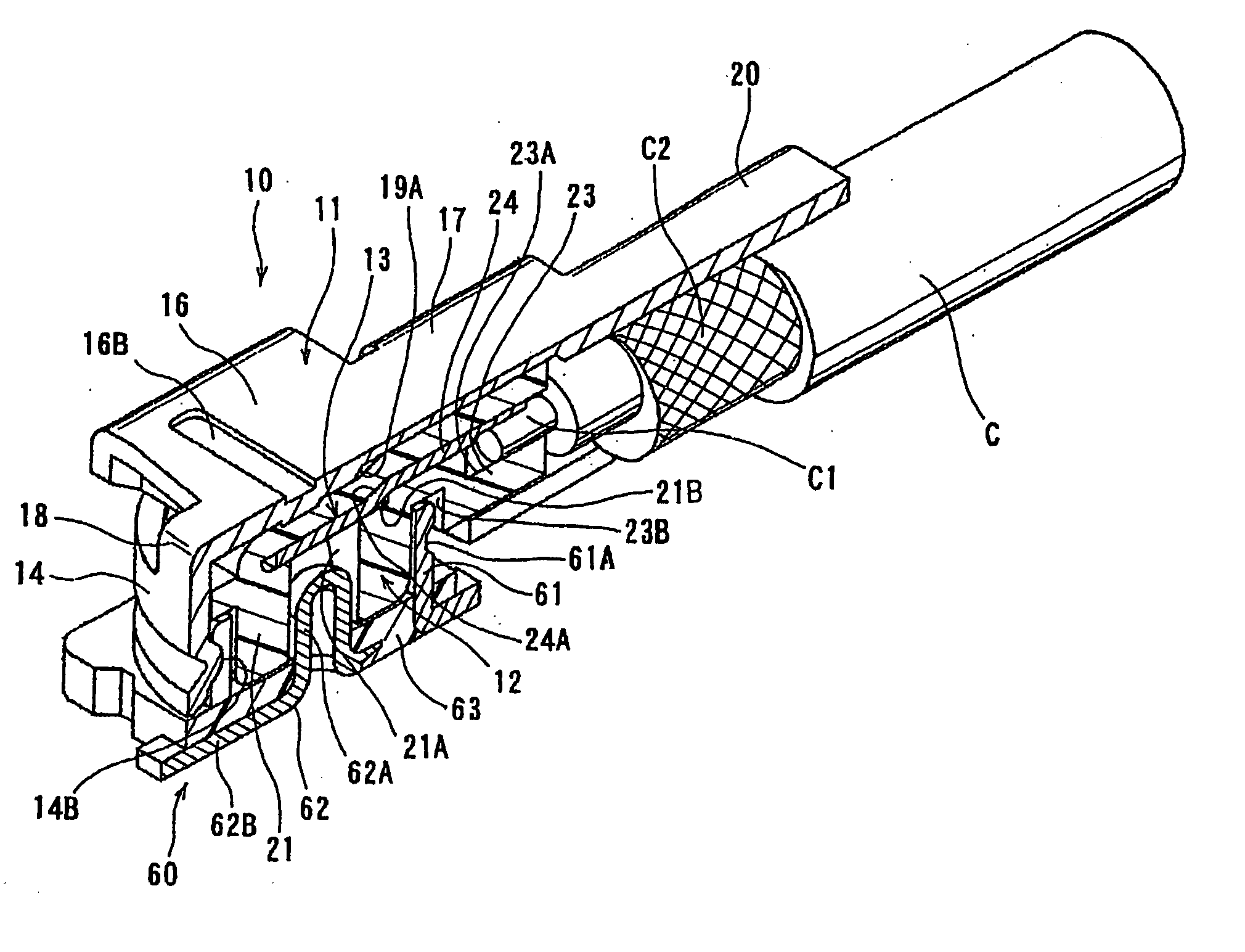
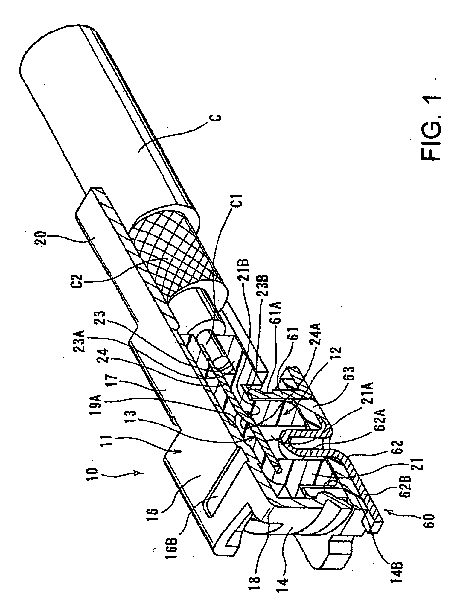
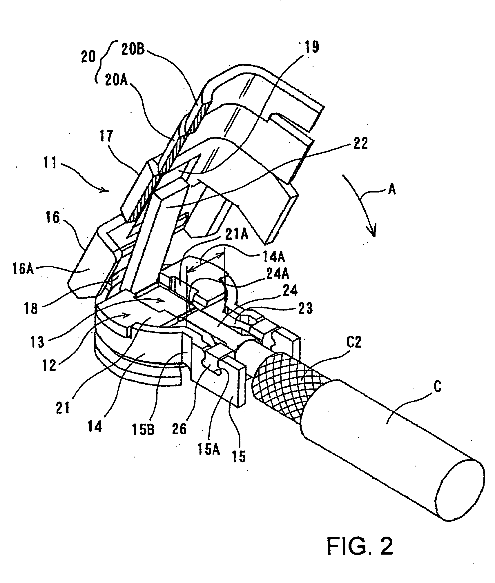
[0033] In FIGS. 1-3, the coaxial connector 10 is to be connected to the counter connector 60 which is mounted onto a circuit board (See FIG. 1). This counter connector 60 is not a part of this invention, and is same as a conventional connector shown in FIG. 5. Therefore, same reference numerals are used for the same parts as in FIG. 5, and the explanation is omitted. The coaxial connector 10 of this embodiment which is to be connected to the counter connector 60 is so-called “right angle connector”, in which the connector fits to the counter connector in the direction perpendicular to the extending direction of the cable. As shown in FIGS. 1 and 2, this connector comprises an outer conductor 11, a dielectric 12 and a terminal 13 which is a center conductor.

[0034] The outer conductor11 is formed by first forming the outer shape by punching and then bending a metal sheet, and has a cylindrical fitting section 14, arms 15, a cover section 16 and a surrounding section 17 as a unitary p...


PUM


Abstract

A coaxial electrical connector includes an outer conductor (11) having a cylindrical fitting section (14) to fit onto the counter connector (60), a dielectric (12) placed in the outer conductor (11) and a center conductor (13) which is held by the dielectric (12). It further includes a cover section (16) to cover the other opened end of the cylindrical fitting section (14), and a surrounding section (17) to surround the cable C, which is connected to the connecting section (24) of the center conductor. The cover section (16) and the surrounding section (17) are bent at a linking section (18). The cover section (16) has a receiving section (19) on the inner surface which contacts with the tongue (22) of the dielectric (12), in order to place at least a part of the tongue (22) therein.

Description

BACKGROUND OF THE INVENTION [0001] 1. Field of the Invention [0002] The present invention relates to a coaxial electrical connector, especially a right angle coaxial electrical connector. [0003] 2. Description of the Related Art [0004] As for the right angle electrical connector, the one disclosed in Patent Reference JP 2001-43939 is known. [0005] As shown in FIG. 5, the connector 50 of the Patent Reference is fitted and connected onto the counter connector 60, which is arranged on a circuit board P, in the direction vertical to the circuit board. The counter connector 60 has a cylindrical outer conductor 61, a center conductor 62 arranged in the center of the outer conductor 61, and a dielectric 63 which is molded between those conductors as a unitary piece. The outer conductor 61 is formed to have a cylindrical shape by rolling and jointing two edges of a metal sheet piece. The outer conductor 61 has a locking groove 61A on the outer circumferential surface. The center conductor 6...

Claims


Application Information

Patent Timeline
IPC IPC(8): H01R13/42H01R13/56H01R103/00
CPCH01R13/42H01R2103/00H01R24/50H01R13/567H01R13/646
Inventor IKEDA, KAZUHIKO
Owner HIROSE ELECTRIC GROUP
Why Eureka
Try Eureka