Unlock instant, AI-driven research and patent intelligence for your innovation.

System for tensioning a coil spring

Inactive Publication Date: 2005-06-30
KLANN SPEZIAL WERKZEUGBAU
View PDF0 Cites 10 Cited by
  • Summary
  • Abstract
  • Description
  • Claims
  • Application Information

AI Technical Summary

Benefits of technology

[0009] Thus, the object of the present invention is to design a system of the type of this class for tensioning a coil spring such that the tensioning device of this system can be passed through extremely narrow through holes of an axle body and a means for securing the two pressure plates against rotation does not have to be omitted.

Problems solved by technology

Because of the guide pipe provided and the elements securing against rotation, which project radially to the outside, the tensioning device has a relatively large external diameter here, so that this tensioning device cannot be used for any application on a motor vehicle.
This means in turn that the diameter of the tensioning device cannot be smaller than a minimum diameter because of the elements securing against rotation, which are provided over the guide pipe.
However, the consequence of this is that the prior-art spring vice must do without a means securing the two pressure plates against rotation in both cases.
However, since this is extremely dangerous for the operating personnel during the operation, such a system for tensioning a coil spring can be used only conditionally.

Method used


Image

  • System for tensioning a coil spring
  • System for tensioning a coil spring
  • System for tensioning a coil spring

Examples


Embodiment Construction

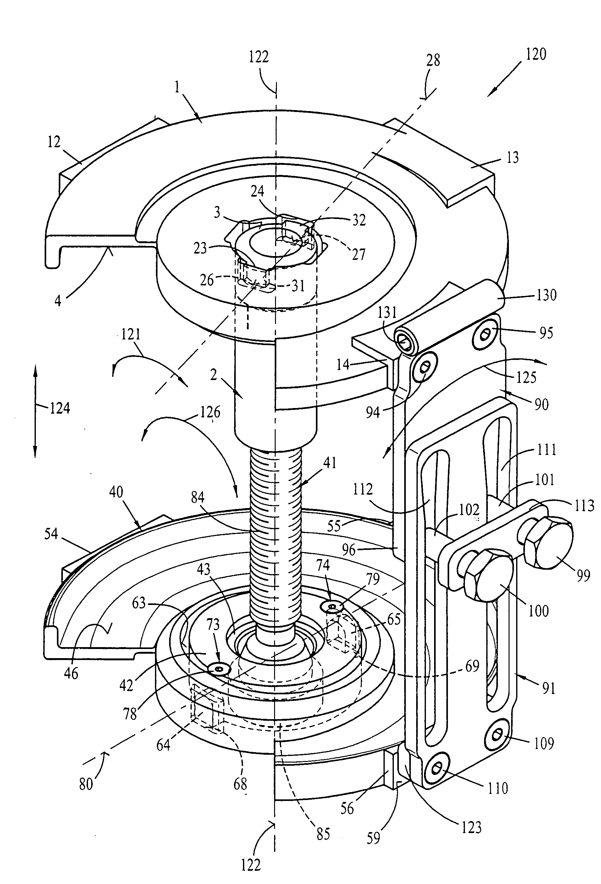
[0057]FIG. 1 shows a perspective top view of a second pressure plate 1 together with a threaded pipe 2. The second pressure plate 1 has an approximately circular base and is provided with a central opening 3 in its center. This second pressure plate 1 forms a tensioning surface 4, which is limited by an edge web 5 in its radially outer edge area, for receiving a spring turn of a coil spring to be tensioned. The tensioning surface 4 is radially limited in its radially inner edge area by an inner edge web 6, which is formed by a central support disk 7.

[0058] As can be recognized from FIG. 1, the central opening 3 is located within this support disk 7, which is arranged concentrically in the pressure plate 1. It can also be recognized from FIG. 1 that the outer edge area of the pressure plate 1, which edge area forms the tensioning surface 4, has a circumferential pitch. The tensioning surface 4 is interrupted by a recess 8, which extends over an angle ″ of about 90E in the circumfere...


PUM

PropertyMeasurementUnit
Lengthaaaaaaaaaa
Thicknessaaaaaaaaaa
Pressureaaaaaaaaaa

Abstract

A system for tensioning a coil spring with a spring vice (120), comprising a first and second pressure plate (40, 1) each, which are disk-shaped or strip-shaped and have a central opening (63, 3) each. The pressure plates (40, 1) can be caused to engage a spring turn of the coil spring each to tension the coil spring. A tensioning device is formed from a threaded pipe and a threaded spindle (41). The threaded spindle (41) has a spindle head (85), which is provided with a wrench profile and via which the threaded spindle (41) is axially supported at the first pressure plate (40) by means of a thrust bearing (43) and wherein the threaded pipe (2) has, at its end located axially opposite the spindle head (85), radially projecting radial fingers (31, 32), by which the threaded pipe (2) can be brought into pulling connection with the second pressure plate (1). To make it possible to embody a tensioning device (2, 41) with the smallest possible diameter, the first pressure plate (40) has a first guide (91) at a radially outer edge area, which can be caused to engage a second guide (90) of the second pressure plate (1). The second guide is arranged in the radially outer edge area of the second pressure plate (1), in an axially adjustable manner. For the pressure plates (1, 40) to be axially adjustable by the two guides (90, 91) and to be connected with one another detachably and nonrotatably in relation to one another.

Description

CROSS REFERENCE TO RELATED APPLICATIONS [0001] This application claims the benefit of priority under 35 U.S.C. § 119 of German Application DE 103 61 597.0 filed Dec. 24, 2003, the entire contents of which are incorporated herein by reference.FIELD OF THE INVENTION [0002] The present invention pertains to a system for tensioning a coil spring with a spring vice, comprising a first and second pressure plate each, which are disk-shaped or strip-shaped and have a central opening each and can be caused to engage a spring turn each of the coil spring for tensioning the coil spring, as well as a tensioning device, which is formed from a threaded pipe and a threaded spindle, wherein the threaded spindle has a spindle head, which is provided with a wrench profile and via which the threaded spindle is axially supported at the first pressure plate by means of a thrust bearing, and wherein the threaded pipe has, at its end located axially opposite the spindle head, radially projecting radial fi...

Claims


Application Information

Patent Timeline
IPC IPC(8): B25B27/30F16F1/12
CPCY10T29/53622B25B27/304
Inventor KLANN, HORST
Owner KLANN SPEZIAL WERKZEUGBAU