
Double clamp vise

a double-clamp, clamping technology, applied in the field of clamping, can solve the problem that the use of the double-clamp vise is still restricted

Inactive Publication Date: 2014-01-23
WANG WEN FENG
View PDF41 Cites 22 Cited by
  • Summary
  • Abstract
  • Description
  • Claims
  • Application Information

AI Technical Summary

Benefits of technology

The patent describes a double clamp vise that can hold two work pieces with different thickness. The vise includes a seat body with two movable jaws that can be moved separately using a screwing rod. The front portion of the screwing rod has a smaller diameter and a step, and is covered by a telescoping screwing tube with a matching outer thread. The two movable jaws are engaged with the screwing rod and screwing tube using the inner and outer threads, and a main spring is compressed between the screwing rod and screwing tube. A crank is connected to the front portion of the screwing rod for rotating it. The technical effect of this invention is that it provides a versatile and efficient tool for holding multiple work pieces that have different thicknesses.

Problems solved by technology

However, a double clamp vise still has a restriction in use: the two clamps cannot hold two work pieces with different thickness.
This really causes a problem.

Method used


Image

  • Double clamp vise
  • Double clamp vise
  • Double clamp vise

Examples


Embodiment Construction

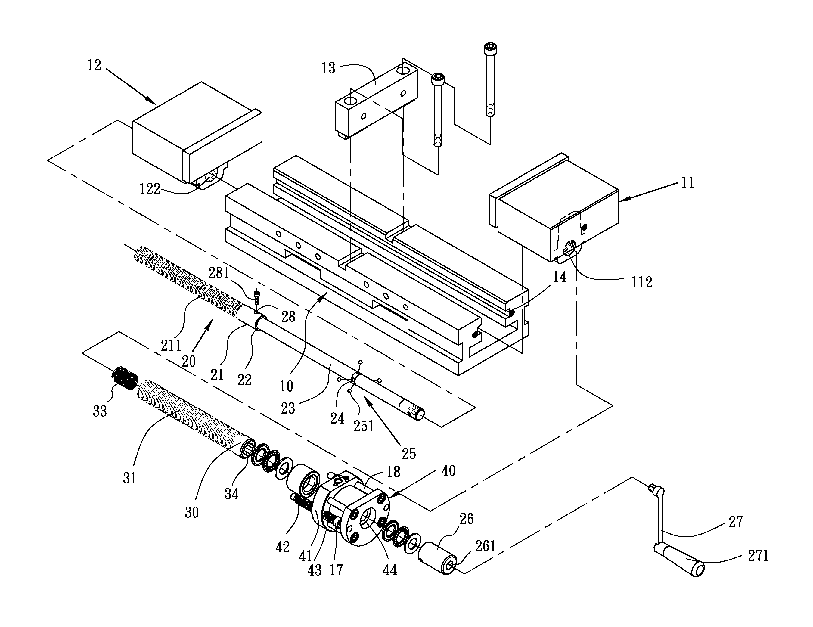
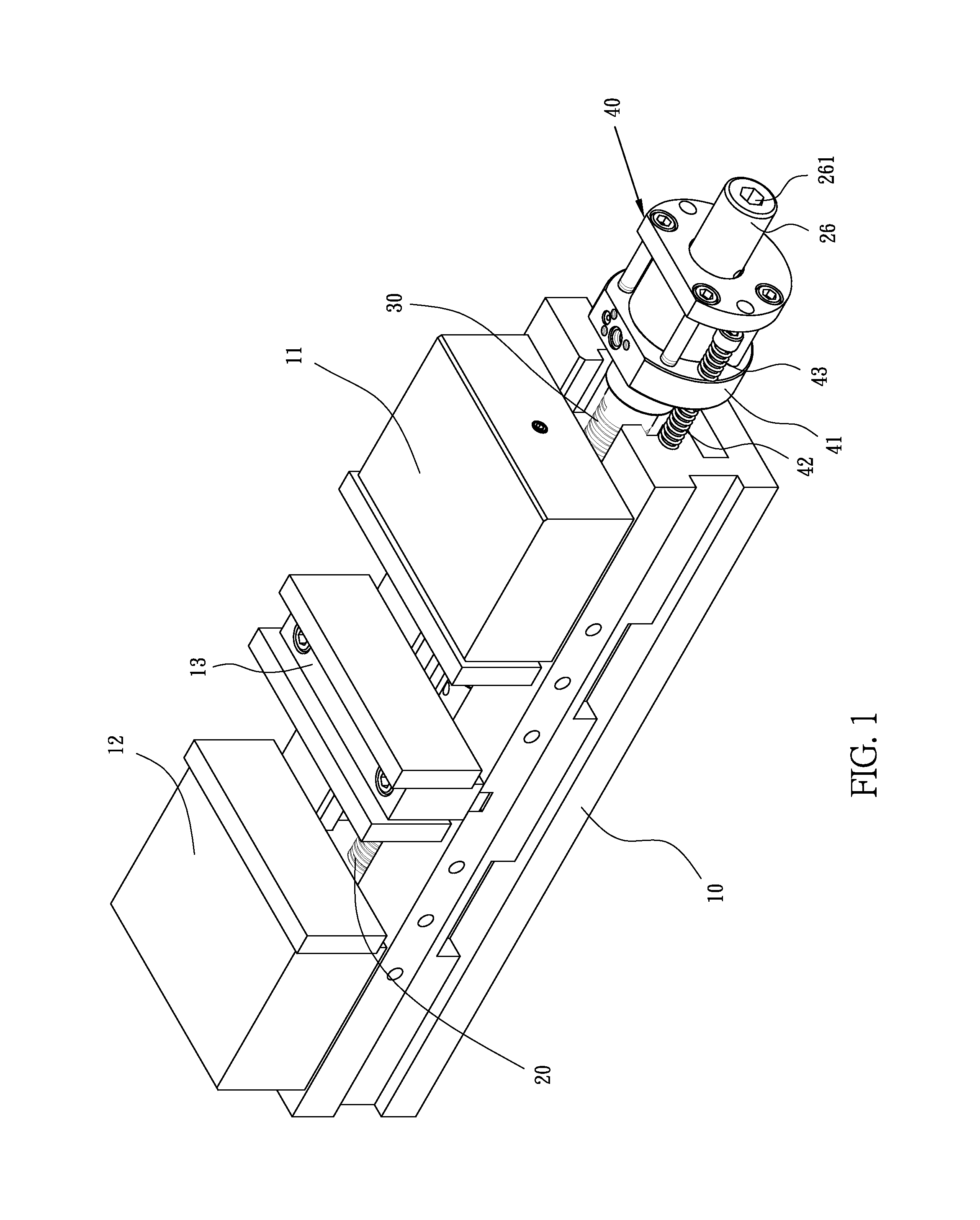
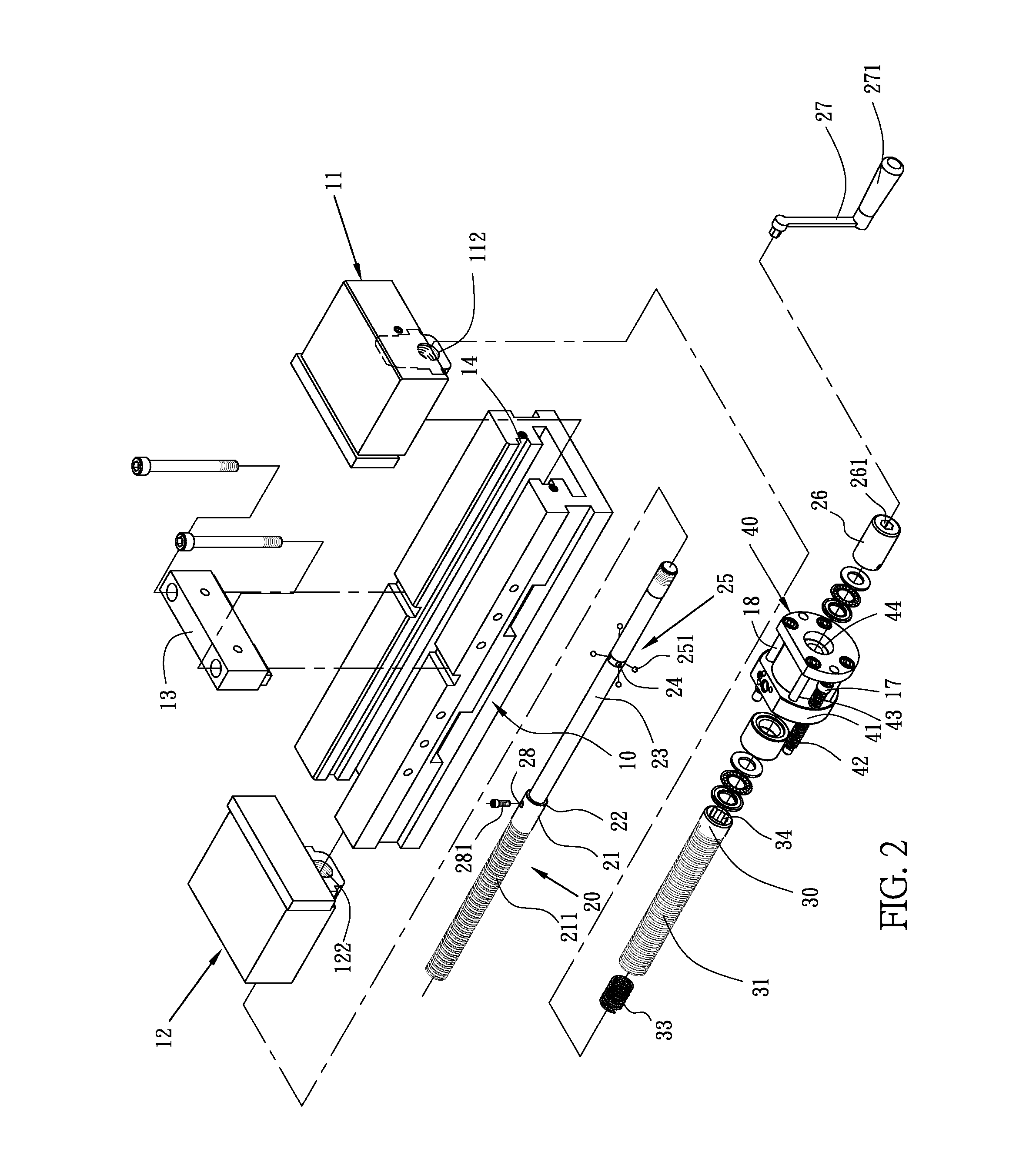
[0014]Please refer to FIGS. 1 and 2. The double clamp vise of the invention includes a seat body 10, a screwing rod 20, a screwing tube 30, a main spring 33, a crank 27 and a power assist module 40.

[0015]The seat body 10 has a rear movable jaw 12, a front movable jaw 11, a fixed jaw 13 between the two movable jaws 11, 12, and a rail 14 for being slidably engaged by the two movable jaws 11, 12. The rear movable jaw 12 and front movable jaw 12 are provided with a first inner thread 122 and a second inner thread 112, respectively.

[0016]The screwing rod 20 is composed of a rear portion 20 and a front portion 23. A diameter of the rear portion 21 is greater than that of the front portion 23. A first outer thread 211 is formed on the rear portion 21. A step 22 is formed between the front portion 21 and the rear portion 23. The rear movable jaw 12 is engaged with the screwing rod 20 by screwing the first outer thread 211 and the first inner thread 122. In other words, the rear portion 21 i...


PUM


Abstract

The vise includes a seat body having two movable jaws separately with two inner threads, a fixed jaw and a rail. A screwing rod has a rear portion and a front portion whose diameter is less than the rear portion. A first outer thread is formed on the rear portion. A step is formed between the front portion and the rear portion. A screwing tube telescopically and unrotatably sheathes the front portion of the screwing rod and has a second outer thread. The two movable jaws are separately engaged with the screwing tube and screwing rod by screwing the outer threads and the inner threads. A spiral direction of the first outer thread is contrary to the second outer thread. A main spring is nipped between the screwing rod and screwing tube. A crank is axially connected to the front portion of the screwing rod for rotating the screwing rod.

Description

BACKGROUND OF THE INVENTION[0001]1. Technical Field[0002]The present invention relates to vises, particularly to double clamp vises.[0003]2. Related Art[0004]A vise or vice is a mechanical screw apparatus used for holding or clamping a work piece to allow work to be performed on it with tools such as saws, planes, drills, mills, screwdrivers, sandpaper, etc. Vises usually have one fixed jaw and another, parallel, jaw which is moved towards or away from the fixed jaw by the screw. A double clamp vise has two movable jaws oppositely beside a fixed jaw. Such a double clamp vise can hold two work pieces at the same time. Thus its working efficiency is double higher than others.[0005]However, a double clamp vise still has a restriction in use: the two clamps cannot hold two work pieces with different thickness. This really causes a problem.SUMMARY OF THE INVENTION[0006]An object of the invention is to provide a double clamp vise which can hold two work pieces with different thickness.[00...

Claims


Application Information

Patent Timeline
IPC IPC(8): B25B1/10B25B1/02
CPCB25B1/103B25B1/18B25B1/2478
Inventor WANG, WEN-FENG
Owner WANG WEN FENG
Learn More