Apparatus for electrophoresis

an apparatus and electrophoresis technology, applied in the field of apparatus for electrophoresis, can solve the problems of inconsistent performance, labour-intensive and time-consuming operation of existing two-dimensional electrophoresis systems, etc., and achieve the effects of improving the reproducibility of the system, improving the reproducibility of the separation process, and positive pressur

Inactive Publication Date: 2005-04-07
PROTEOME SYSTEMS INTELLECTUAL PROPERTY PTY LTD
View PDF4 Cites 15 Cited by
  • Summary
  • Abstract
  • Description
  • Claims
  • Application Information

AI Technical Summary

Benefits of technology

[0014] One advantage of the present invention is that unlike the apparatus described in PCT / AU00 / 01065, the tray does not require any electrodes as these are provided by the lid of the apparatus / cassette. Since manual placement of the electrodes is not required this enhances the reproducability of the separation process.
[0015] The IPG is held in position by the depending bars (IPG holder bars), thus, maintaining positive contact between the IPG and the filter paper, which hence, maintains a consistent electric field through the IPG strip. The apparatus also provides a consistent distance between the IPG strip and the electrode, thus improving reproducability of the system.
[0016] It is preferred that the electrode bars and / or IPG holder bars are mounted on biasing means such as springs to ensure positive pressure on the IPG strip and filter paper and to accommodate different thicknesses of filter paper.
[0017] It is envisaged that in a modification of the present invention, the lid could be modified to provide individually addressable electrodes for each of the grooves in the tray wherein the lower edge of the depending electrode bars and the IPG holder bars are all crenellated. In this manner, the lid of the cassette provides an individual pair of opposed electrodes for each of the IPGs running in the tray, and the voltage between each of the pairs of electrodes can be controlled independently of the voltage between other opposed electrode pairs.
[0018] The tray such as those described in PCT / AU00 / 01065 in the name of the present applicant, the contents of which are incorporated here by reference, may be used in the apparatus of the present invention. However, the apparatus could be used to accommodate trays running may different types of gels and any open topped type of gel which is not enclosed in glass or plastic plates or the like, such as second dimension type SDS PAGE gel, agarose DNA type gel, starch gels, polyacrylamide carrier ampholyte IEF gels could be used. Such gels could be accommodated in a gel-side-up or a gel-side-down configuration without substantially changing the cassette.

Problems solved by technology

Existing two-dimensional electrophoresis systems are labour-intensive and time-consuming to operate.
There are problems with the consistent and correct location of electrodes relative to the IPG strip, and with sufficiency of electrical contact between the strip and the electrode, and this leads to inconsistent performance and results.

Method used


Image

  • Apparatus for electrophoresis
  • Apparatus for electrophoresis
  • Apparatus for electrophoresis

Examples


first embodiment

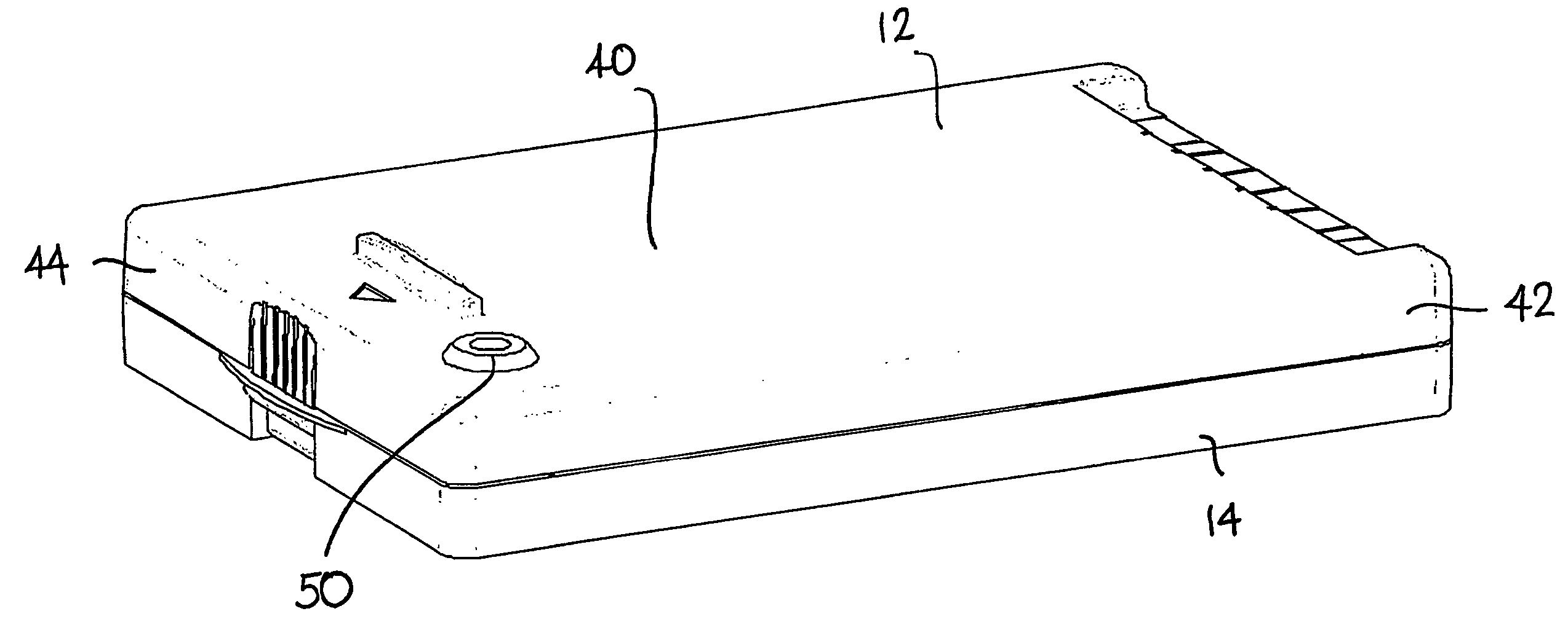
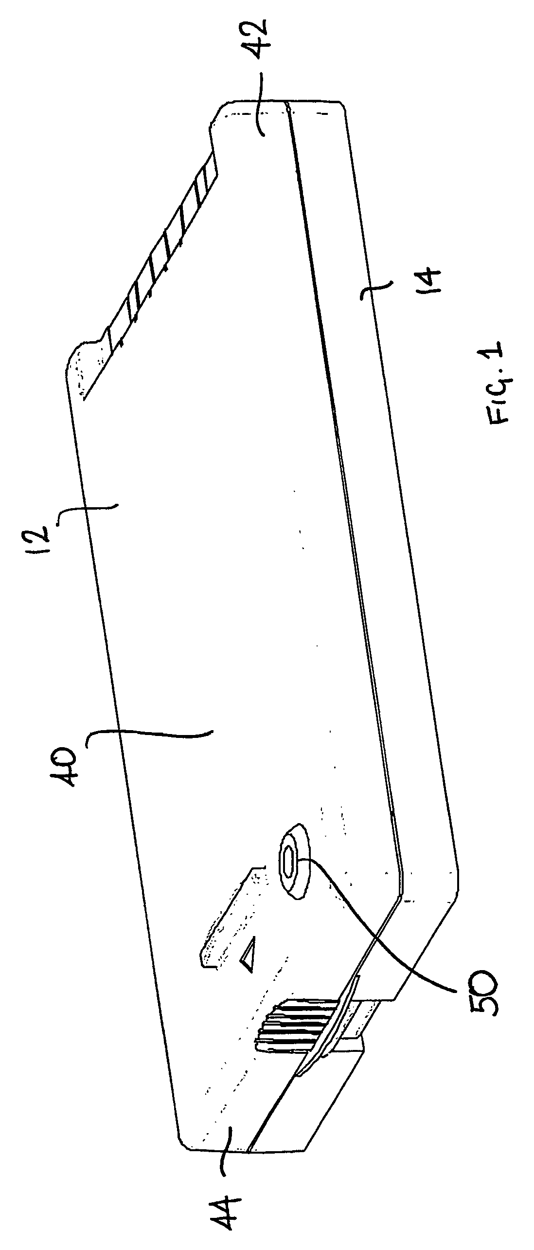
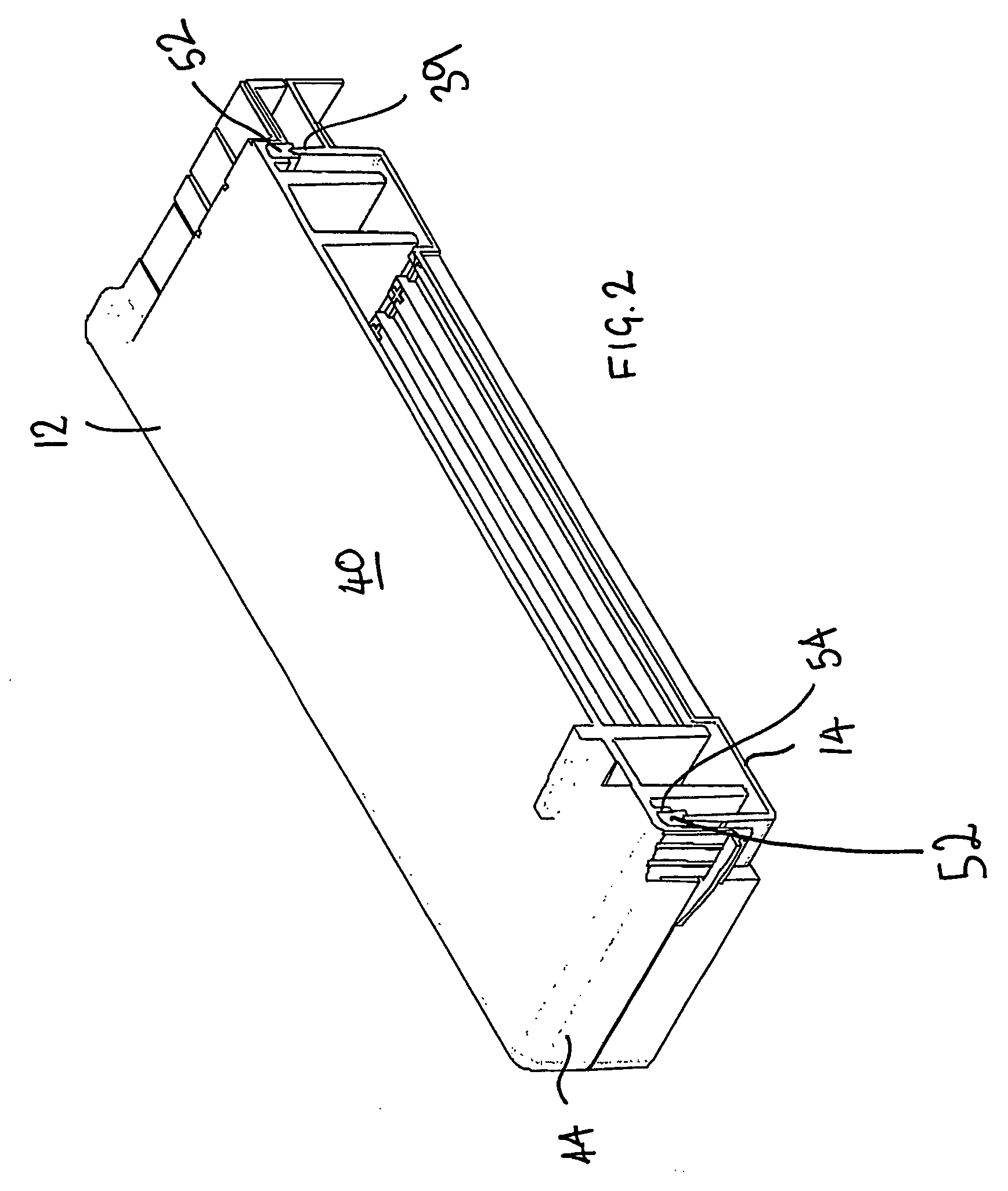
[0031] Referring to the drawings, FIGS. 1 to 5 show a apparatus 10 embodying the present invention. The apparatus includes a lid 12 and a base 14. The base 14 which is best seen in FIGS. 2 and 4 comprises a simple generally rectangular frame defining four sides 16, 18, 20 and 22 and inwardly directed flange 24 extending to an integrally moulded tray 26. The base is typically made in one piece from a moulded plastics material.

[0032] The tray 26 defines twelve elongate parallel grooves or troughs 28. However the tray could have more or less than twelve troughs. The troughs shown in FIG. 4 are about 6 mm wide, however the troughs may be relatively narrower or relatively wider than 6 mm. As is best seen in FIG. 5 each trough 28 has a base or floor 30 which is stepped at each end defining an end wall 32 which serves to contain rehydration fluid for rehydrating an IPG strip within the trough. The wall is about 1 mm above the floor of the trough. There is an electrode bridge region 34 on t...

second embodiment

[0036] Referring to the drawings, FIGS. 6 to 10 show an apparatus 100 embodying the present invention comprising a lid 102 and a base 104. In this embodiment the base and tray are not integrally moulded, and the base is in the form of a frame 104 for receiving a separate IPG tray 105 (refer to FIG. 10). The base 104, best seen in FIG. 9, is a simple generally rectangular frame 104 defining four sides 106, 108, 110 and 112 providing an open central area 114. An inwardly extending ledge 116 supports the outer edges of the tray 105 when the tray is located in central area of the frame and holds the tray 105 in the correct position to receive the lid 102. The tray 105 is typically made from a moulded plastics material. The base 104 is open to allow the base of the IPG tray 105 to directly contact a cooling surface, such as a peltier cooling surface or any other suitable cooling surface on which the tray may rest, in use.

[0037] Two prongs 118 and 120 extend away from one side 112 of the ...


PUM

PropertyMeasurementUnit
thicknessaaaaaaaaaa
pressureaaaaaaaaaa
electrophoresisaaaaaaaaaa

Abstract

An apparatus for electrophoresis comprises a base incorporating an integral or separable tray defining a plurality of parallel troughs into which IPG strips may be placed is disclosed. The apparatus further includes a lid. The lid has a top and depending sides and is configured to fit over the base. The lid defines at least one opposed pair of depending electrodes, and also, spaced inwardly of the electrodes relative to the sides of the lid, a pair of opposed depending members for applying pressure to IPG strips located in use, in troughs of the tray. In a variant the lid provides individually addressable electrodes for each of the grooves in the tray wherein the lower edge of the depending electrode bars and the IPG holder bars are all crenellated. In this manner, the lid of the cassette provides an individual pair of opposed electrodes for each of the IPGs running in the tray, and the voltage between each of the pairs of electrodes can be controlled independently of the voltage between other opposed electrode pairs.

Description

FIELD OF THE INVENTION [0001] This invention relates to an apparatus for use in electrophoresis. In particular the invention relates to a cassette for use in electrophoresis comprising a tray for holding IPG strips and an associated cover, and the use of the same for separating macromolecules by electrophoresis. BACKGROUND OF THE INVENTION [0002] In the field of analysing macromolecules, one dimensional and two dimensional gel electrophoresis have become the standard tools for separating and visualising macromolecules. Typical applications of electrophoresis include separating proteins from complex mixtures such as tissue samples, bacteria or plant material. As used herein, the term macromolecule includes but is not limited to proteins including serum and cell proteins, bacterial proteins, non-histone chromatin proteins, ribosomal proteins, mixtures of ribonucleo-proteins and ribosomal proteins, glycoproteins, and nucleic acids. Currently, the highest resolution method for separatin...

Claims


Application Information

Patent Timeline
Patent Type & Authority Applications(United States)
IPC IPC(8): B01D53/32B03C5/00C25B9/17G01N27/447
CPCG01N27/44773G01N27/44704
Inventor HUNTER, WILLIAMRUMMERY, GERARD MICHAELHERBERT, BENJAMIN ROSSDURACK, MATTHEW C.A.
Owner PROTEOME SYSTEMS INTELLECTUAL PROPERTY PTY LTD
Why Eureka
Try Eureka