Projection optical system and projection television employing the same

Inactive Publication Date: 2005-06-30
SAMSUNG ELECTRONICS CO LTD
View PDF8 Cites 4 Cited by
  • Summary
  • Abstract
  • Description
  • Claims
  • Application Information

AI Technical Summary

Benefits of technology

[0006] The present invention provides a projection optical system which is less costly to manufacture an

Problems solved by technology

The conventional lens system, however, has complicated lens structures.
In addition, since the conventional lens system is manufactured through compression molding, the manufacturing costs are

Method used


Image

  • Projection optical system and projection television employing the same
  • Projection optical system and projection television employing the same
  • Projection optical system and projection television employing the same

Examples


Embodiment Construction

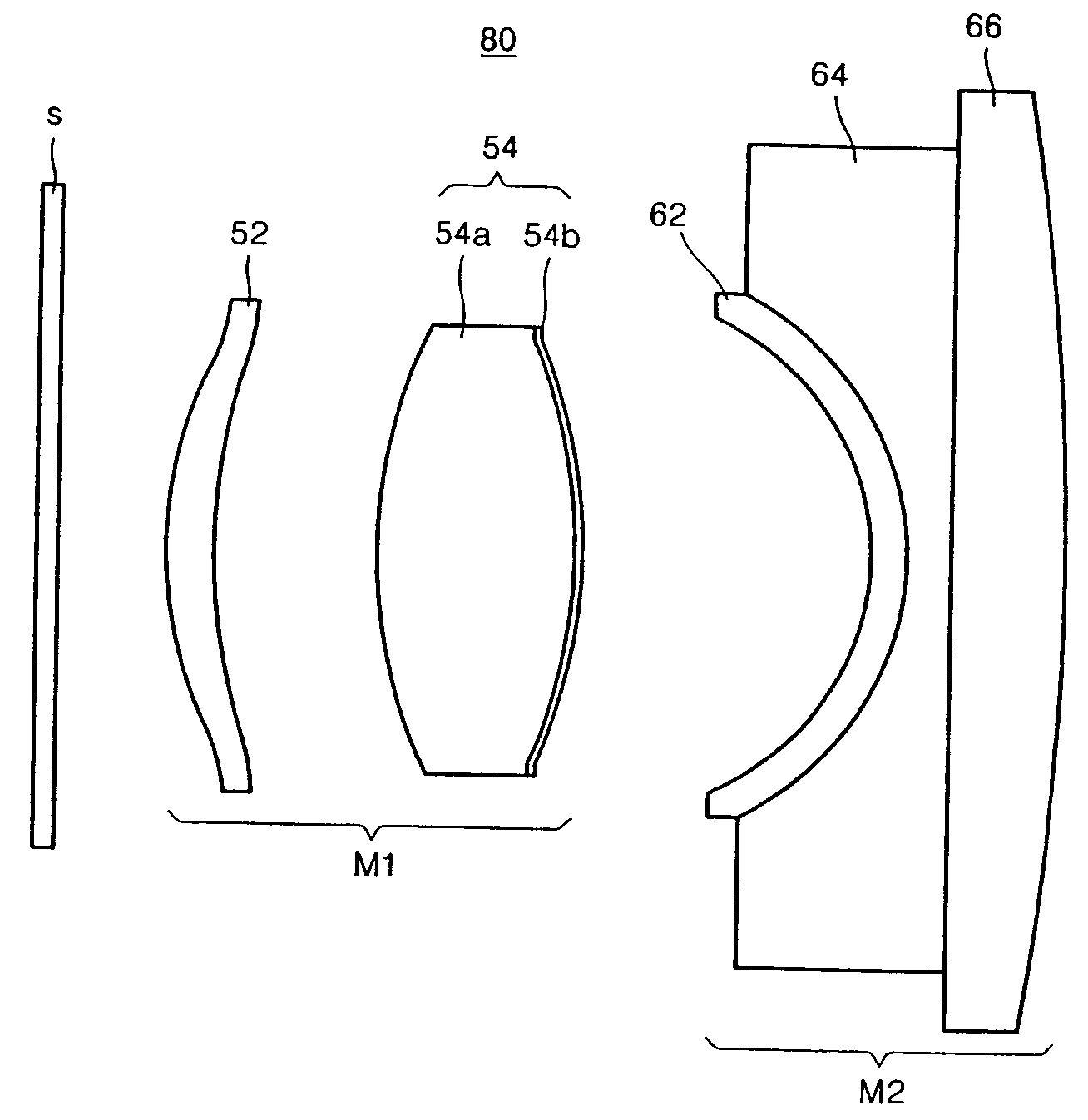
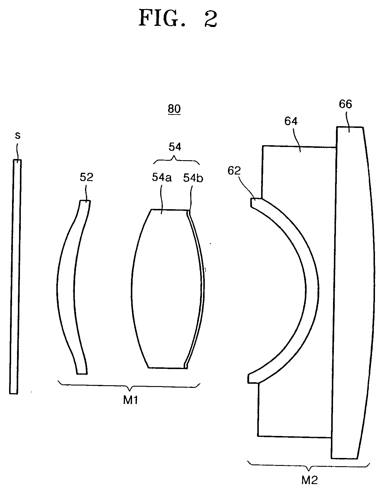
[0016] Referring to FIG. 2, a projection optical system 80 includes a lens module M1 and an electron beam tube optical module M2.

[0017] The lens module M1 includes a plastic power lens 52 and a hybrid lens 54. The hybrid lens 54 is comprised of a spherical glass lens 54a, which is a biconvex lens, and an aspheric lens layer 54b, which is coated on at least one surface of the spherical glass lens 54a.

[0018] Preferably, but not necessarily, both surfaces of the spherical glass lens 54a are symmetrical, and the aspheric lens layer 54b is formed of a plastic layer so that its aspheric surfaces face the electron beam tube optical module M2. The focal power of the hybrid lens 54 has a ratio of 0.95-0.98 to the focal power of the entire projection optical system.

[0019] The aspheric lens layer 54b has an aspheric surface expressed by Equation (1): z=c⁢ ⁢ρ21+1-(1+k)⁢c2⁢ρ2+∑i=17⁢ ⁢ai⁢ρ2⁢i(1)

where z denotes a longitudinal coordinate of the aspheric surface, c denotes a curvature of the as...


PUM


Abstract

A projection optical system and a projection television employing the same are provided. The projection optical system includes a lens module and an electron beam tube optical module. The lens module includes a plastic power lens and a hybrid lens. The hybrid lens includes a spherical, biconvex, glass lens and an aspheric lens layer formed on at least one face of the spherical lens. The electron beam tube optical module includes a C-shaped aberration correction device, a window, and a coolant disposed between the window and the aberration correction device. Accordingly, the projection television can provide high quality pictures. In addition, it is possible to reduce the manufacturing costs of the projection television.

Description

BACKGROUND OF THE INVENTION [0001] This application claims the benefit of Russian Patent Application No. 2003131819, filed on Oct. 30, 2003, in the Russian Patent and Trademark Office, the disclosure of which is incorporated herein in its entirety by reference. FIELD OF THE INVENTION [0002] The present invention relates to a projection optical system and a projection television (TV) employing the same. More particularly, the present invention relates to a projection optical system having a simplified lens system structure, thus reducing the manufacturing costs and satisfactorily correcting aberration, and to a projection television employing the projection optical system. DESCRIPTION OF THE RELATED ART [0003] A conventional projection lens system disclosed in U.S. Pat. No. 5,029,993 magnifies an image formed by a cathode ray tube (CRT) and then projects the magnified image on a screen. FIG. 1 is a diagram illustrating the conventional projection lens system. Referring to FIG. 1, the...

Claims


Application Information

Patent Timeline
IPC IPC(8): G02B13/00G02B9/00G02B13/16H01J29/89H04N5/74H04N9/31
CPCG02B13/16H01J29/894H04N9/3141H04N9/31H04N5/7408H04N5/74
Inventor YOON, SEOK-ILHWANG, GYU-HWANSHIRANKOV, ALEXANDER FEDOROVICHPOZDNYAKOV, VADIM VICTOROVICHKHOROKHOROV, ALEXEY MIKHAILOVICHFROLOV, MAXIM EVGUENYEVICH
Owner SAMSUNG ELECTRONICS CO LTD
Why Eureka
Try Eureka