Spherical aberration correction apparatus

Inactive Publication Date: 2006-09-19
PIONEER CORP
View PDF3 Cites 6 Cited by
  • Summary
  • Abstract
  • Description
  • Claims
  • Application Information

AI Technical Summary

Benefits of technology

[0009]The present invention has been made in view of the foregoing problems, and the problems that the invention intends to solve include the above problem as an example. It is an object of the present invention to provide a high-performance aberration correction apparatus which can ext

Problems solved by technology

However, the apparatus has drawbacks that the beam expander causes an increased size of an optical system.
In addition, a mechanism for driving a lens is necessary, which leads to a complicated structure.
In particular, in a case of use in the multi-layer disc, the thickness of the liquid crystal must be extremely increased, and a large applied voltage is required.
Therefore, in addition to difficulty in fabrication, there has been a drawback o

Method used


Image

  • Spherical aberration correction apparatus
  • Spherical aberration correction apparatus
  • Spherical aberration correction apparatus

Examples


first embodiment

[0026

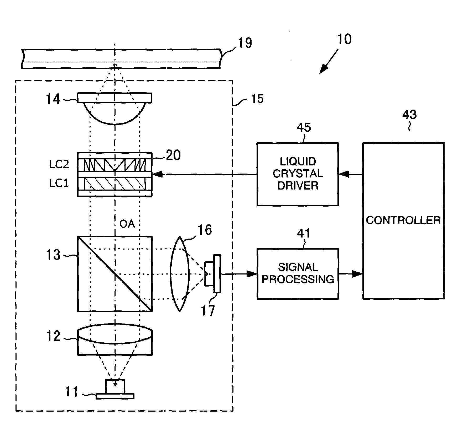
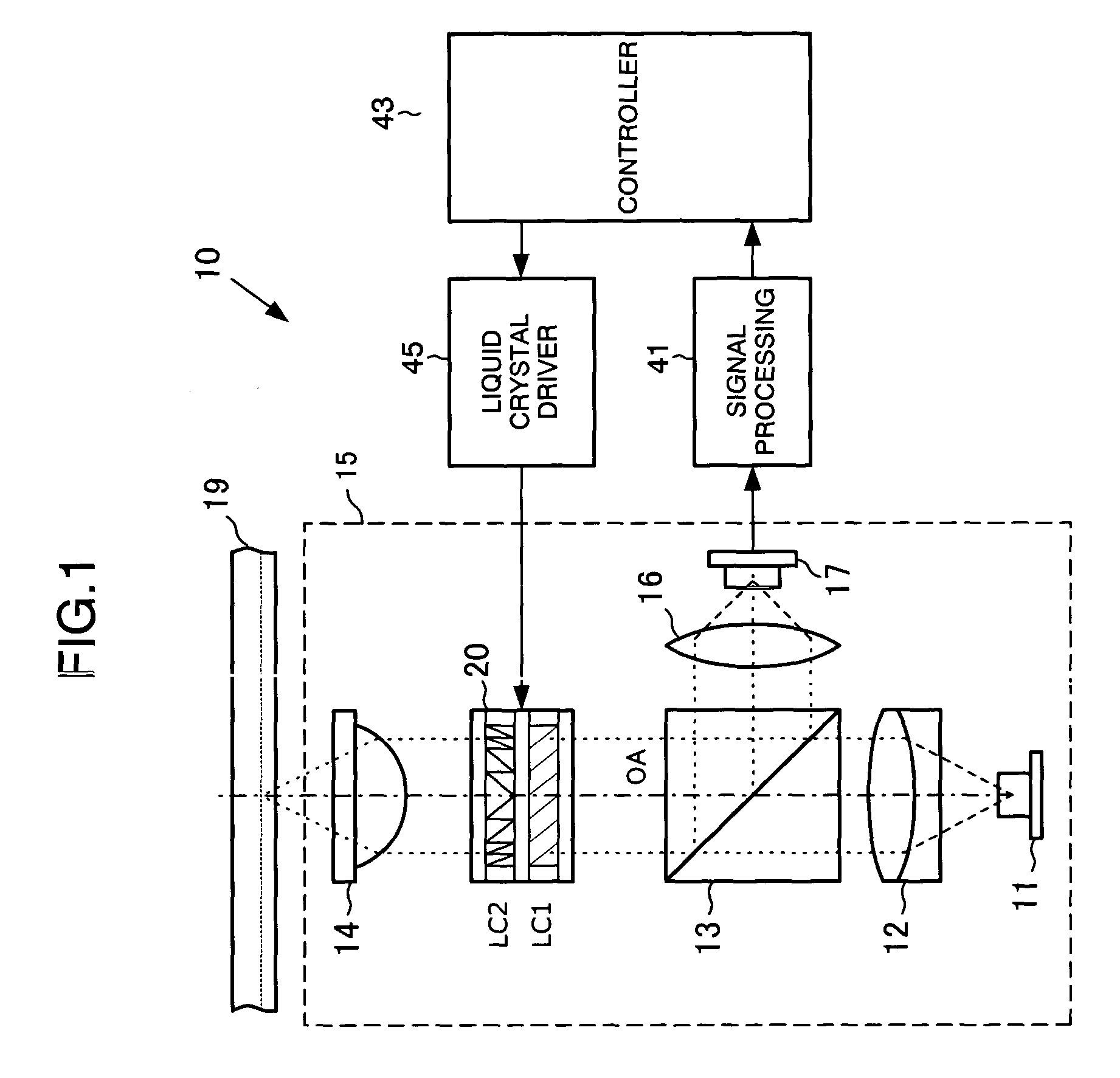
[0027]FIG. 1 is a block diagram showing a configuration of an aberration correction apparatus 10 according to a first embodiment of the present invention.

[0028]There is provided a laser light source 11 emitting a laser light having a predetermined wavelength in an optical pickup device 15. The laser light source 11 emits a laser light, for example, having a wavelength λ of 405 nanometers (nm). The light beam emitted from the laser light source 11 is made into a parallel light beam by a collimator lens 12. The light beam is incident on an optical disc 19 by way of a beam splitter 13, an aberration correction unit 20, and an object lens 14. The incident light beam is reflected by the optical disc 19. The reflected light is reflected by the beam splitter 13 after passing through the object lens 14 and the aberration correction unit 20, and condensed by a condensing lens 16 to be detected by an optical detector 17.

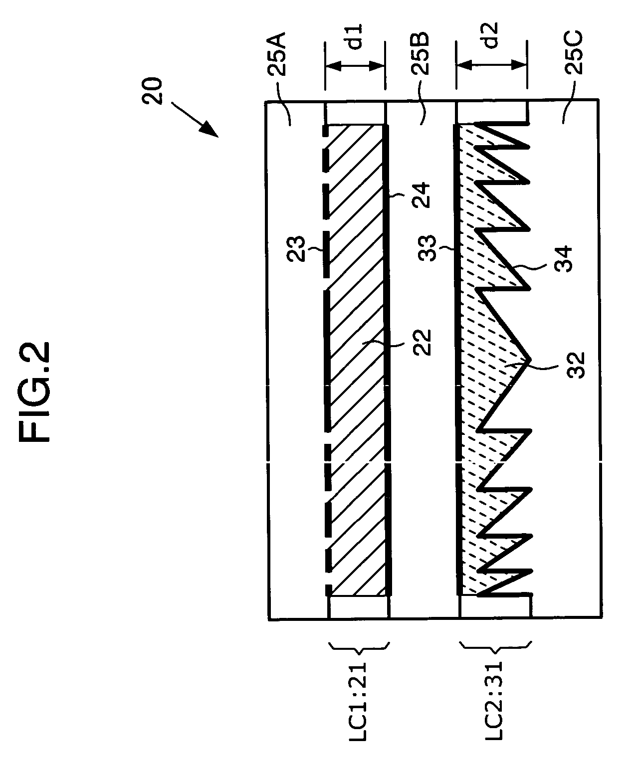
[0029]The aberration correction unit 20 will be described in detail ...

second embodiment

[0068

[0069]FIG. 13 is a block diagram showing a configuration of an optical pickup 15 in the aberration correction apparatus 10 according to a second embodiment of the present invention. In the embodiment, an optical unit 61 for the coarse adjustment of the aberration correction is used instead of the hologram liquid crystal cell 31 in the above-described first embodiment.

[0070]More specifically, the optical unit 61 comprises a glass plate 61A, a concave lens 61B, and a convex lens 61C. The glass plate 61A, the concave lens 61B, and the convex lens 61C are mounted on an actuator (not shown), and driven by the control signal from the controller 43, and either one of the lenses is switched to be arranged on the light axis (OA).

[0071]An aberration correction operation in the embodiment is described below. In the aberration correction for the single-layer disc, as the first embodiment, after the focus-close and tracking-close to the recording layer has been completed, the glass plate 61...


PUM


Abstract

An aberration correction apparatus includes a first aberration correction element having aberration correction portions, a second aberration correction element which causes the wave front of the transmitted light beam to have a blaze hologram shape, a discriminator which discriminates the aberration of the reflected light beam, a coarse phase adjuster which drives the second aberration correction element on the basis of the magnitude of the aberration of the reflected light beam, and a fine phase adjuster which corrects aberration remained after the aberration correction by the coarse phase adjuster.

Description

BACKGROUND OF THE INVENTION[0001]1. Field of the Invention[0002]The present invention relates to a spherical aberration correction apparatus for correcting aberration of a light beam.[0003]2. Description of the Related Art[0004]As a data recording medium wherein data recording or data reproduction is performed optically, an optical disc such as CD (Compact Disc) or DVD (Digital Video Disc or Digital Versatile Disc) is known. Various kinds of optical discs have been developed including a read-only optical disc, a write-once optical disc on which data can be recorded additionally, and a rewritable optical disc in which data erasing and rewriting can be performed. Furthermore, a multi-layer optical disclaimed to increase capacity of the optical disc is known, in which recording capacity for one side of the recording disc can be increased by providing multiple recording layers on a same recording side. Such multi-layer optical disc has a structure such that the multiple recording layers...

Claims


Application Information

Patent Timeline
IPC IPC(8): G11B7/00G11B7/125G11B7/09G11B7/135G11B7/1369G11B7/1378G11B7/1392
CPCG11B7/0948G11B7/1369G11B7/13927G11B7/1378G11B2007/0013
Inventor OGASAWARA, MASAKAZU
Owner PIONEER CORP
Why Eureka
Try Eureka