Optical imaging lens and imaging equipment

An optical imaging lens and imaging surface technology, applied in the field of imaging lenses, can solve problems such as difficulty in meeting the requirements of preview distance, reducing target recognition range, poor imaging effect, etc. The effect of stability

Active Publication Date: 2021-11-05
JIANGXI LIANCHUANG ELECTRONICS CO LTD
View PDF5 Cites 0 Cited by
  • Summary
  • Abstract
  • Description
  • Claims
  • Application Information

AI Technical Summary

Problems solved by technology

At present, vehicle-mounted lenses used for target recognition in front of vehicles are often designed for short-distance targets, and their field of view is relatively large. Although this type of lens can better image short-distance targets, it cannot image distant target

Method used


Image

  • Optical imaging lens and imaging equipment
  • Optical imaging lens and imaging equipment
  • Optical imaging lens and imaging equipment

Examples


Example

[0083] first embodiment

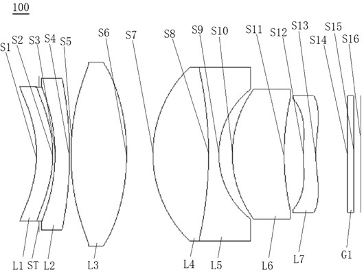
[0084] see figure 1 , which is a schematic structural view of the optical imaging lens 100 provided by the first embodiment of the present invention, the optical imaging lens 100 includes in sequence from the object side to the imaging surface along the optical axis: a first lens L1, a stop ST, and a second lens L2 , the third lens L3, the fourth lens L4, the fifth lens L5, the sixth lens L6, the seventh lens L7, and the filter G1.

[0085] The first lens L1 has positive refractive power, the object side S1 of the first lens is concave, and the image side S2 of the first lens is convex.

[0086] The second lens L2 has negative refractive power, the object side S3 of the second lens is concave, and the image side S4 of the second lens is convex.

[0087] The third lens L3 has positive refractive power, and both the object side S5 and the image side S6 of the third lens are convex.

[0088] The fourth lens L4 has positive refractive power, and both t...

Example

[0101] second embodiment

[0102] see Figure 4 , is a schematic structural diagram of the optical imaging lens 200 provided by the second embodiment of the present invention. The optical imaging lens 200 in this embodiment is roughly the same as the optical imaging lens 100 in the first embodiment, the difference is that the sixth lens L6 of the optical imaging lens 200 in this embodiment is a biconvex lens, and the seventh lens The object side S12 is a concave surface, the image side S13 of the seventh lens is a convex surface at the near optical axis, the third lens L3 is a glass spherical lens, and the curvature radius and material selection of other lenses are different. The relevant parameters of each lens are shown in Table 3. Show.

[0103] table 3

[0104]

[0105] The parameters of each lens aspheric surface of the optical imaging lens 200 in this embodiment are shown in Table 4.

[0106] Table 4

[0107]

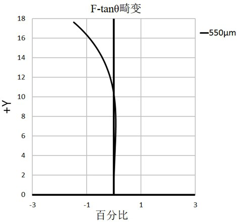
[0108] see Figure 5 , shows the F-tanθ distorti...

Example

[0110] third embodiment

[0111] see Figure 7 , is a schematic structural diagram of the optical imaging lens 300 provided by the third embodiment of the present invention. The optical imaging lens 300 in this embodiment is roughly the same as the optical imaging lens 100 in the first embodiment, the difference is that the stop ST of the optical imaging lens 300 in this embodiment is between the second lens L2 and the third lens Between L3, the first lens L1 is a negative refractive lens, the third lens L3 is a glass spherical lens, and the radius of curvature and material selection of each lens are different. The relevant parameters of each lens are shown in Table 5.

[0112] table 5

[0113]

[0114] The parameters of each lens aspheric surface of the optical imaging lens 300 of this embodiment are shown in Table 6.

[0115] Table 6

[0116]

[0117] see Figure 8 , shows the F-tanθ distortion diagram of the optical imaging lens 300 provided by the third embodime...


PUM


Abstract

The invention discloses an optical imaging lens and imaging equipment. The optical imaging lens sequentially comprises, from an object side to an imaging surface, a first lens with focal power, wherein the object side surface is a concave surface, and the image side surface is a convex surface; a second lens with negative focal power, wherein the object side surface is a concave surface, and the image side surface is a convex surface; a third lens with positive focal power, wherein the object side surface and the image side surface are convex surfaces; a fourth lens with positive focal power, wherein the object side surface and the image side surface are convex surfaces; a fifth lens with negative focal power, wherein the object side surface and the image side surface are concave surfaces, and the fourth lens and the fifth lens form a balsaming lens group; a sixth lens with positive focal power, wherein the object side surface is a convex surface; a seventh lens with negative focal power; and a diaphragm located between the first lens and the third lens, wherein the seven lenses are all glass lenses. The optical imaging lens has the advantages of high pixel, long focal length, large aperture and small distortion.

Description

technical field [0001] The invention relates to the technical field of imaging lenses, in particular to an optical imaging lens and imaging equipment. Background technique [0002] With the development of autonomous driving technology, ADAS (Advanced Driver Assistant System, Advanced Driver Assistance System) has become the standard configuration of many cars; among them, the on-board camera lens, as a key component of ADAS, can sense the road conditions around the vehicle in real time and realize the The performance of functions such as collision warning, lane departure warning, and pedestrian detection directly affects the safety factor of ADAS. Therefore, the performance requirements of on-board camera lenses are getting higher and higher. [0003] The optical lens installed in ADAS and applied to the front of the vehicle is mainly to identify the situation in front of the car. It is required to clearly distinguish obstacles from 100 meters away and realize collision warn...

Claims


Application Information

Patent Timeline
IPC IPC(8): G02B13/00G02B13/18G02B1/00
CPCG02B13/0045G02B13/18G02B13/006G02B1/00
Inventor 王昆魏文哲王克民曾吉勇
Owner JIANGXI LIANCHUANG ELECTRONICS CO LTD
Why Eureka
Try Eureka