
Motion simulator

a simulator and motion technology, applied in the field of motion simulators, can solve the problems of undesired acceleration, delay in decline in the actuality experienced by the passenger, so as to prevent undesired acceleration and reduce the time taken to track the intended moving sensation, the effect of increasing the actuality of the movement of the passenger

Inactive Publication Date: 2005-06-30
SIMULINE
View PDF27 Cites 2 Cited by
  • Summary
  • Abstract
  • Description
  • Claims
  • Application Information

AI Technical Summary

Benefits of technology

[0034] The present invention has been made to overcome the above-mentioned problems, and accordingly, it is an object of the present invention to provide a motion simulator that allows moving sensations similar to the intended sensations and which reduces tracking time, through the elimination of undesired moving sensations when creating moving sensations using gravity.
[0037] The second driving means includes a plurality of roll / pitch actuators connecting the movable frame and the operating chamber, and a universal joint connected between the operating chamber and the movable frame, for limiting an unintended movement of the operating chamber with respect to the movable frame.
[0046] In other words, since the A×Rpv vector is in the same direction as that of the acceleration sensations that are intended to be created, undesired accelerating sensations are prevented during the creation of the accelerating sensation using force of gravity, and as a result, the time taken to track the intended moving sensations is shortened, and the moving actuality experience by the passenger is increased.

Problems solved by technology

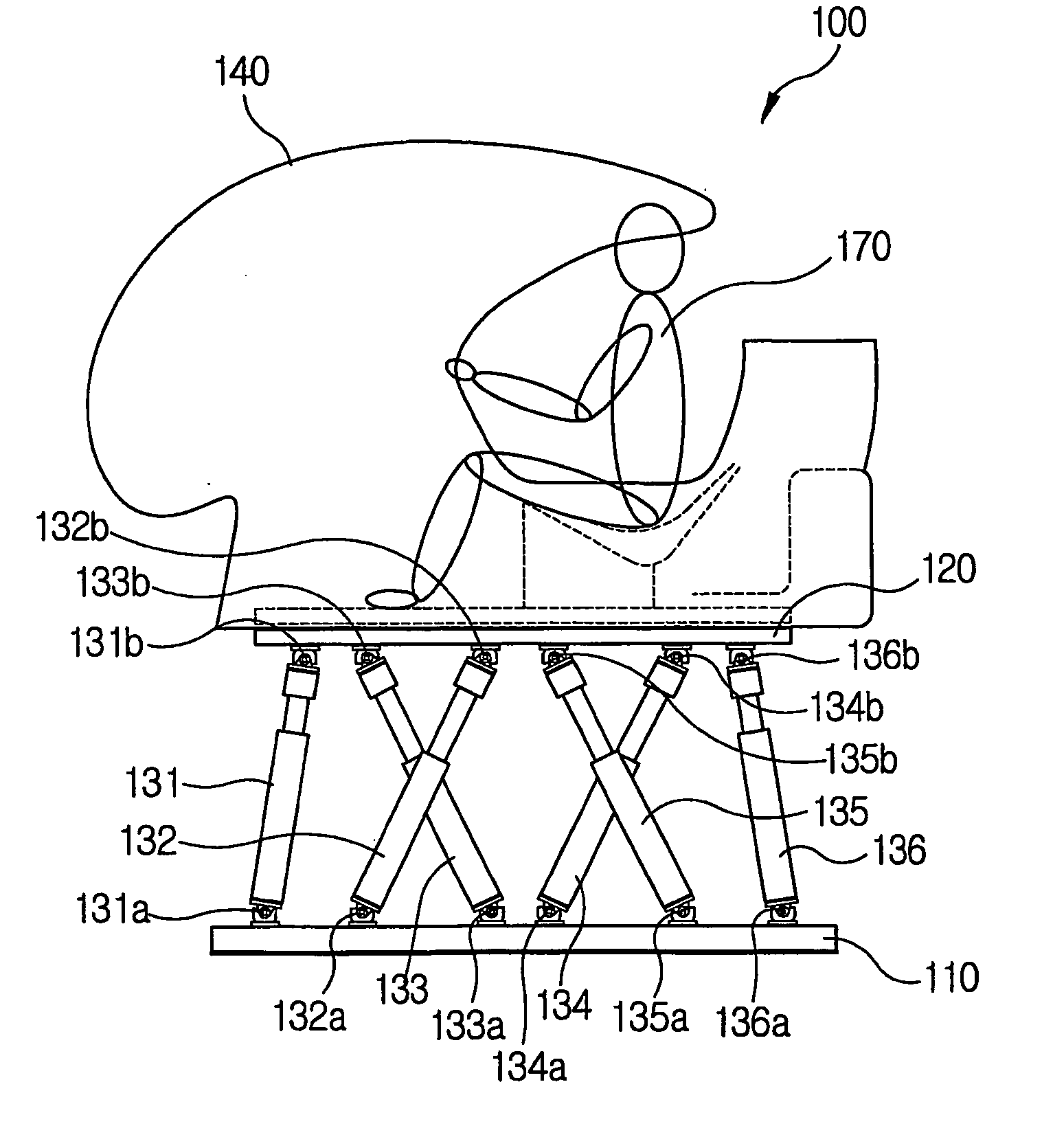
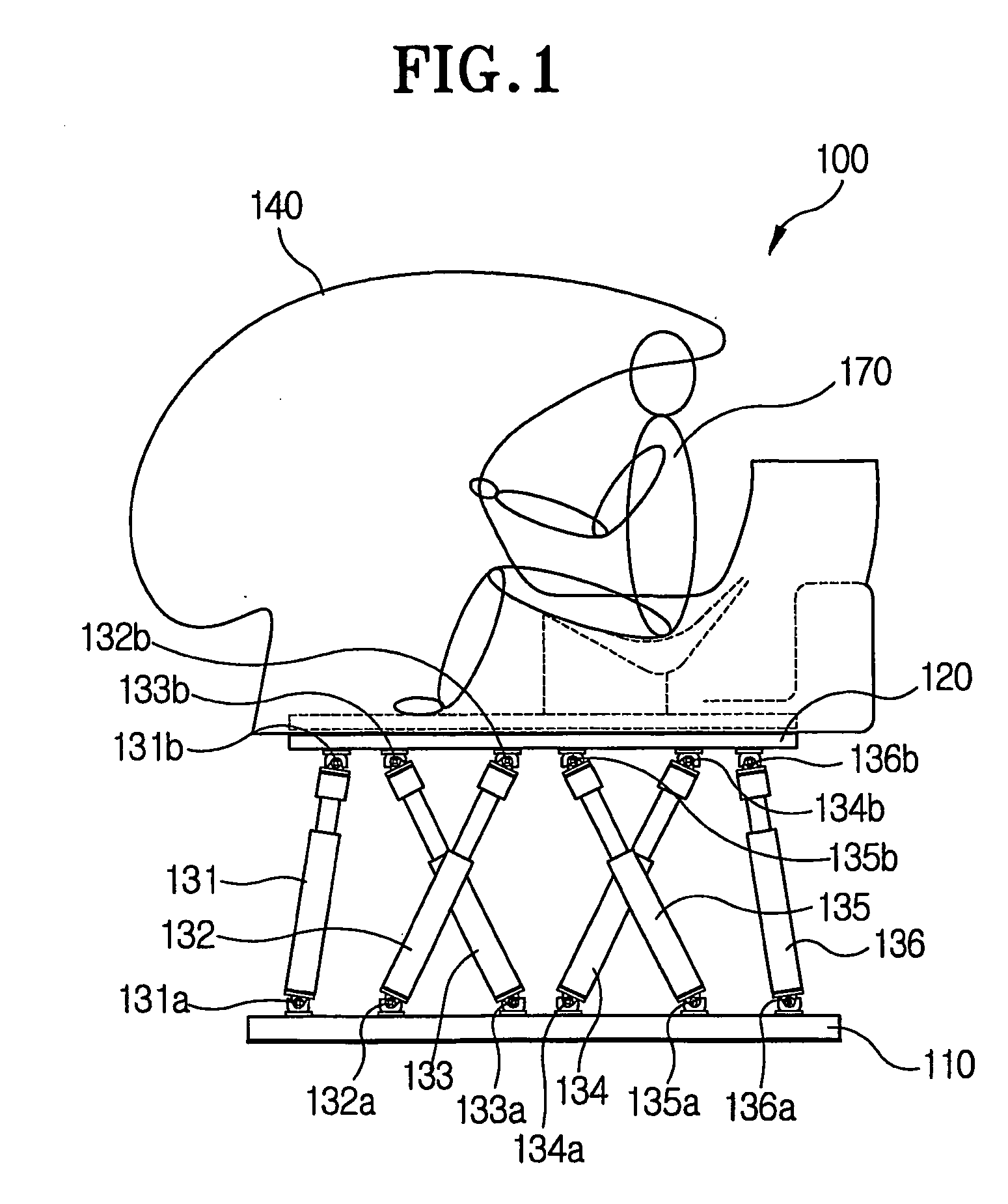
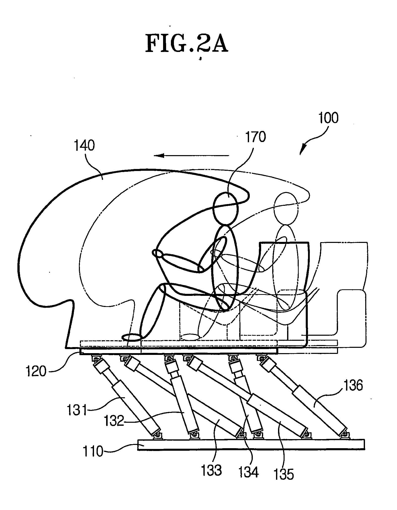
Due to the above, when representing acceleration from continuous linear acceleration or from centrifugal motion to the side direction, that is, when the movable frame 120 is tilted to utilize gravity, there is the problem of occurrence of undesired acceleration.
As a result of such problems, as shown by the solid line of FIG. 7, a moving sensation in the opposite direction of the moving sensation intended to be created (dotted line of FIG. 7) is applied, and furthermore, the time taken to track the intended moving sensation is delayed.
This means a decline in actuality experienced by the passenger.
However, although the extent may vary, the above mentioned problems of conventional motion simulators occur in all motion simulators having different degrees of freedom.

Method used


Image

  • Motion simulator
  • Motion simulator
  • Motion simulator

Examples


Embodiment Construction

[0061] The preferred embodiments of the present invention are described in detail with reference to the annexed drawings.

[0062] Referring to FIG. 8, the motion simulator according to one preferred embodiment of the present invention includes a stationary frame 210, a movable frame 220 pivotally formed on the stationary frame 210, an operating chamber 230 arranged at a lower side of one end of the movable frame 220, a first driving means for pivoting the movable frame 220, and a second driving means for moving the operating chamber 230 with respect to the movable frame 220.

[0063] The stationary frame 210 is installed fixedly against the ground (gravity field). The stationary frame 210 includes a bottom support 211 at the bottom, and a sidewall support 213 upwardly extended from the bottom support 211. An end of the sidewall support 213 is branched into two ends pivotally supporting the movable frame 220.

[0064] The movable frame 220 is pivotally connected with the sidewall support ...


PUM


Abstract

A motion simulator includes a stationary frame, a movable frame pivotally connected with the stationary frame, an operating chamber formed at a lower side of one end of the movable frame, a first actuator for pivoting the movable frame, and a second actuator arranged between the operating chamber and the movable frame, for rotating the operating chamber in forward and backward directions with respect to the movable frame.

Description

CROSS-REFERENCE TO RELATED APPLICATIONS [0001] This application is a continuation of International application PCT / KR02 / 02246 filed Nov. 29, 2002, the entire content of which is expressly incorporated herein by reference thereto.TECHNICAL FIELD [0002] The present invention relates to a motion simulator, and more particularly, it relates to an improved motion simulator in which occurrence of undesired moving sensations are eliminated during the creation of moving sensations using gravity and thereby creation of a moving sensation which is more similar to the actual situation is possible. BACKGROUND ART [0003] Generally, a motion simulator refers to a device which simulates motions of objects in a wide space such as an airplane or an automobile and allows people to feel similar moving sensations within a limited space. [0004] As a general motion simulator such as the above, a 6 DOF (degree of freedom) motion simulator 100 in which a movable frame 120 is driven by six actuators 131, 13...

Claims


Application Information

Patent Timeline
Patent Type & Authority Applications(United States)
IPC IPC(8): G09B9/042G09B9/02G09B9/08G09B9/12
CPCG09B9/12G09B9/02G09B9/08
Inventor KIM, EUI-SOK
Owner SIMULINE
Learn More