
High speed shielded internal cable/connector

Inactive Publication Date: 2005-06-30
INTEL CORP
View PDF7 Cites 48 Cited by
  • Summary
  • Abstract
  • Description
  • Claims
  • Application Information

AI Technical Summary

Problems solved by technology

However, if there is a certain amount of EMI emission being generated from the internal cable / connector, then the cable / connector has to meet FCC open box EMI containment requirement.

Method used


Image

  • High speed shielded internal cable/connector
  • High speed shielded internal cable/connector

Examples


Embodiment Construction

[0008] In the following description, for purposes of explanation and not limitation, specific details are set forth such as particular structures, architectures, interfaces, techniques, etc. in order to provide a thorough understanding of the various aspects of the invention. However, it will be apparent to those skilled in the art having the benefit of the present disclosure that the various aspects of the invention may be practiced in other examples that depart from these specific details. In certain instances, descriptions of well-known devices, circuits, and methods are omitted so as not to obscure the description of the present invention with unnecessary detail.

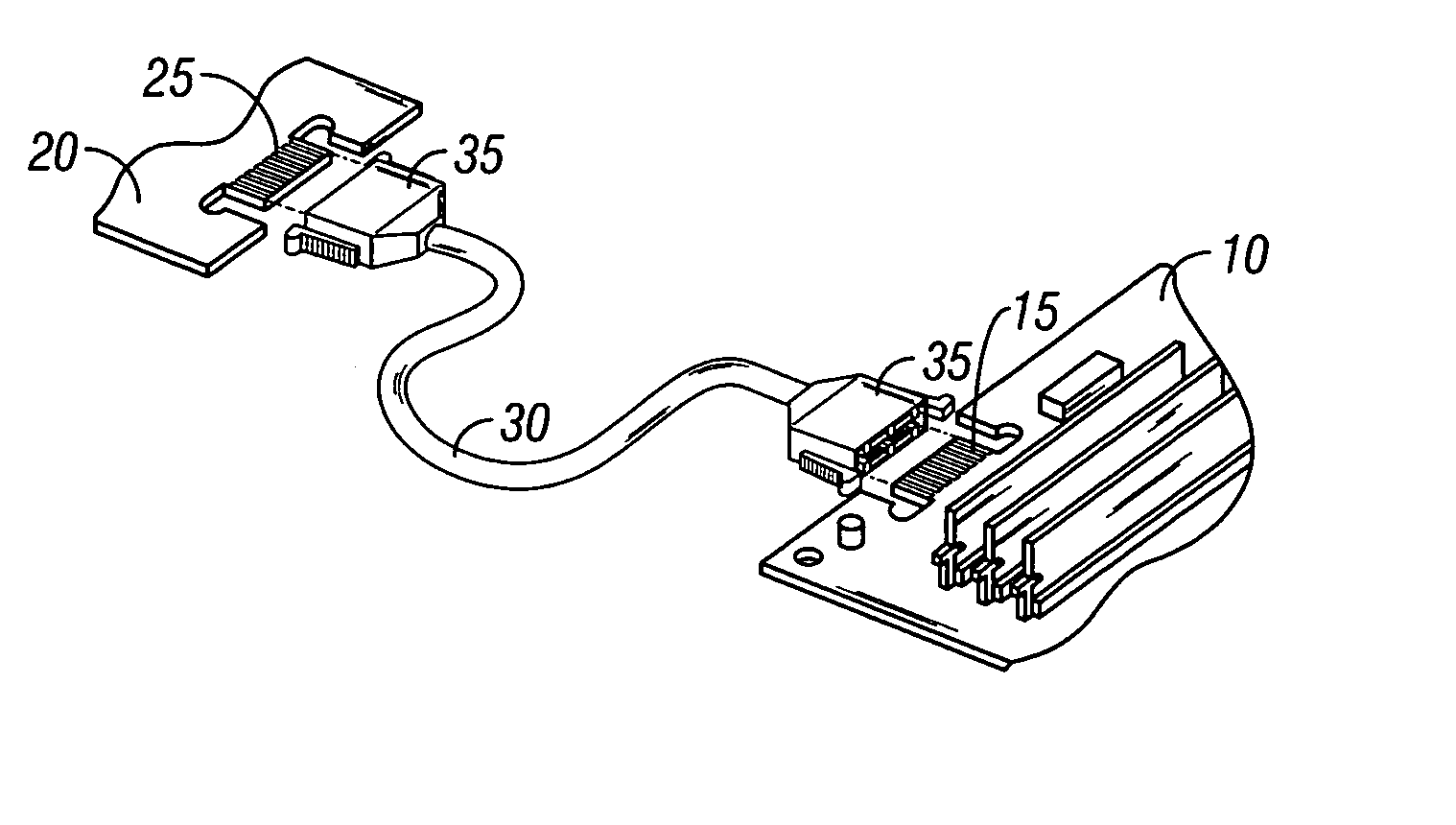
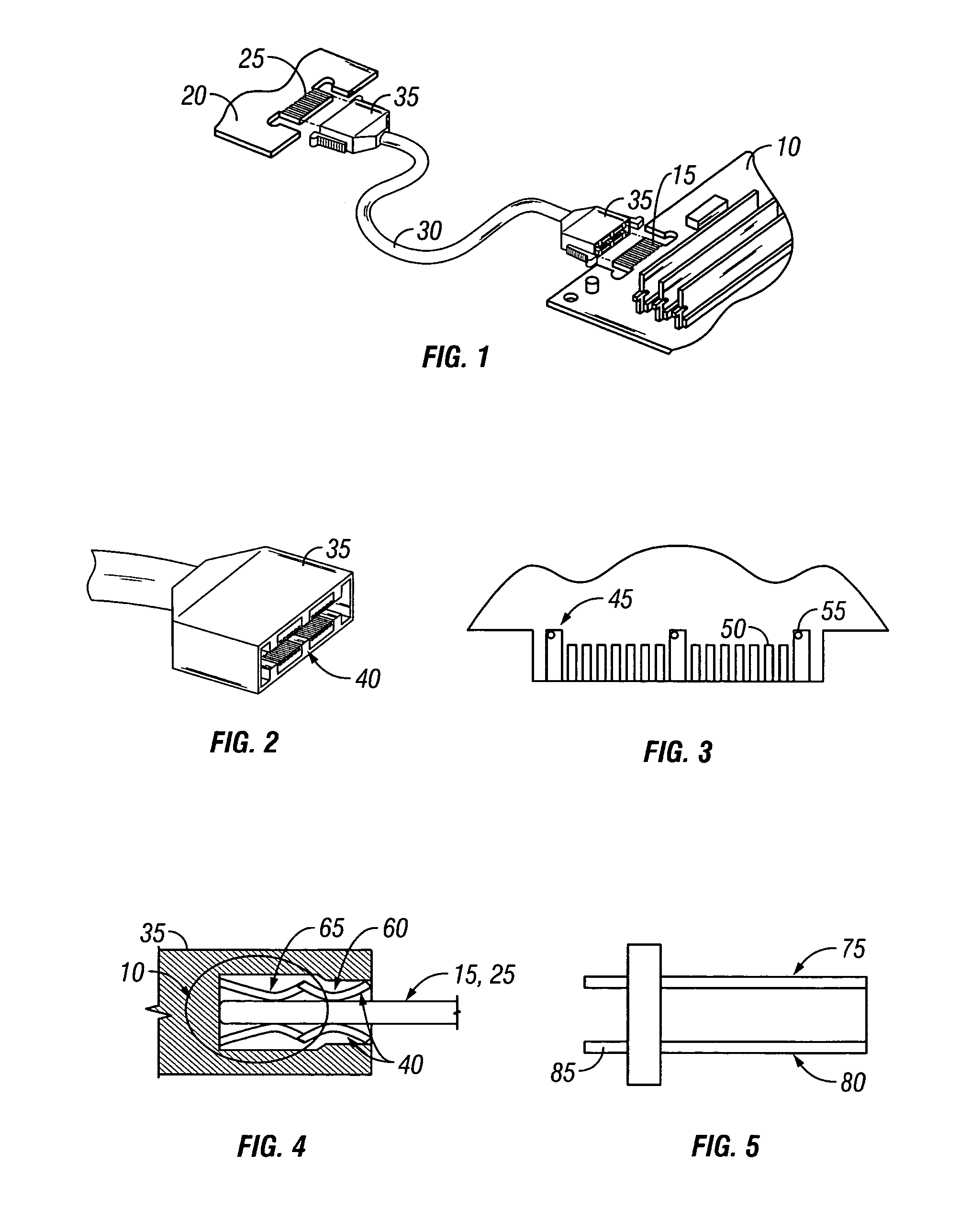
[0009]FIG. 1 is a perspective view of a cable assembly of the present invention. A motherboard 10 includes edge fingers 15 and a daughter card 20 includes edge fingers 25. The edge fingers 15, 25 are located directly on the motherboard 10 and the daughter card 20. A cable assembly 30 includes connectors 35 on either end...


PUM


Abstract

A high speed shielded internal cable / connector is provided. The cable assembly includes a shielded connector on either end of the cable assembly that mates with edge fingers on a motherboard or a daughter card. The one piece card edge style for the cable assembly makes it possible to eliminate the connectors on the motherboard or on the daughter card. The innovative scheme of terminating the cable connector to the system ground makes it possible to shield only the cable assembly and no shielding on the edge fingers.

Description

BACKGROUND INFORMATION [0001] Typically, internal cable / connectors are unshielded and do not require metal shielding around connectors. One example of an internal cable / connector that is unshielded is ATA. However, if there is a certain amount of EMI emission being generated from the internal cable / connector, then the cable / connector has to meet FCC open box EMI containment requirement. This open box EMI containment requirement states that if a certain amount of EMI emission is being generated then the internal cable / connector will require metal shielding. Thus, a need exists for a low cost, shielded internal cable / connector that meets FCC EMI containment requirement.BRIEF DESCRIPTION OF THE DRAWINGS [0002] Various features of the invention will be apparent from the following description of preferred embodiments as illustrated in the accompanying drawings, in which like reference numerals generally refer to the same parts throughout the drawings. The drawings are not necessarily to ...

Claims


Application Information

Patent Timeline
IPC IPC(8): H01R12/16H01R12/18H01R13/648
CPCH01R12/721H01R23/6873H01R13/658
Inventor LING, YUNNOBLE, SCOTTTONG, THAI D.
Owner INTEL CORP
Learn More