Tooless coaxial connector

a coaxial connector, tooless technology, applied in the direction of connections, basic electric elements, electric devices, etc., can solve the problems of time-consuming stripping of the cable end, requiring some training to do properly, and requiring unwanted removal, so as to prevent unwanted removal, reduce the cost of using the connector, and be easy to attach

Inactive Publication Date: 2005-04-14
BELDEN INC
View PDF34 Cites 44 Cited by
  • Summary
  • Abstract
  • Description
  • Claims
  • Application Information

AI Technical Summary

Benefits of technology

[0014] The present invention also allows for the coaxial cable to be held securely within the tooless coaxial connector to prevent the coaxial cable from being inadvertently pulled out of the tooless coaxial connector.
[0015] The present invention is constructed to have a lock ring that securely holds the tooless coaxial connector on the cut end of the coaxial shielded cable to prevent unwanted removal.
[0016] The present invention can be easily attached without extensive training to further lower the cost of using the connector.
[0017] The present invention can be easily removed from the coaxial shielded cable and transferred to another coaxial shielded cable.

Problems solved by technology

A problem with current coaxial connectors is that in order to properly attach the connector to the cable, the cable end must be stripped and prepared.
A problem associated with current coaxial connectors is that the steps of stripping the cable end are time consuming and require some training to do properly.
In addition, the coaxial connector requires the use of a specialized crimping tool which increases the time and expense of using the coaxial connector.

Method used


Image

  • Tooless coaxial connector
  • Tooless coaxial connector
  • Tooless coaxial connector

Examples


Embodiment Construction

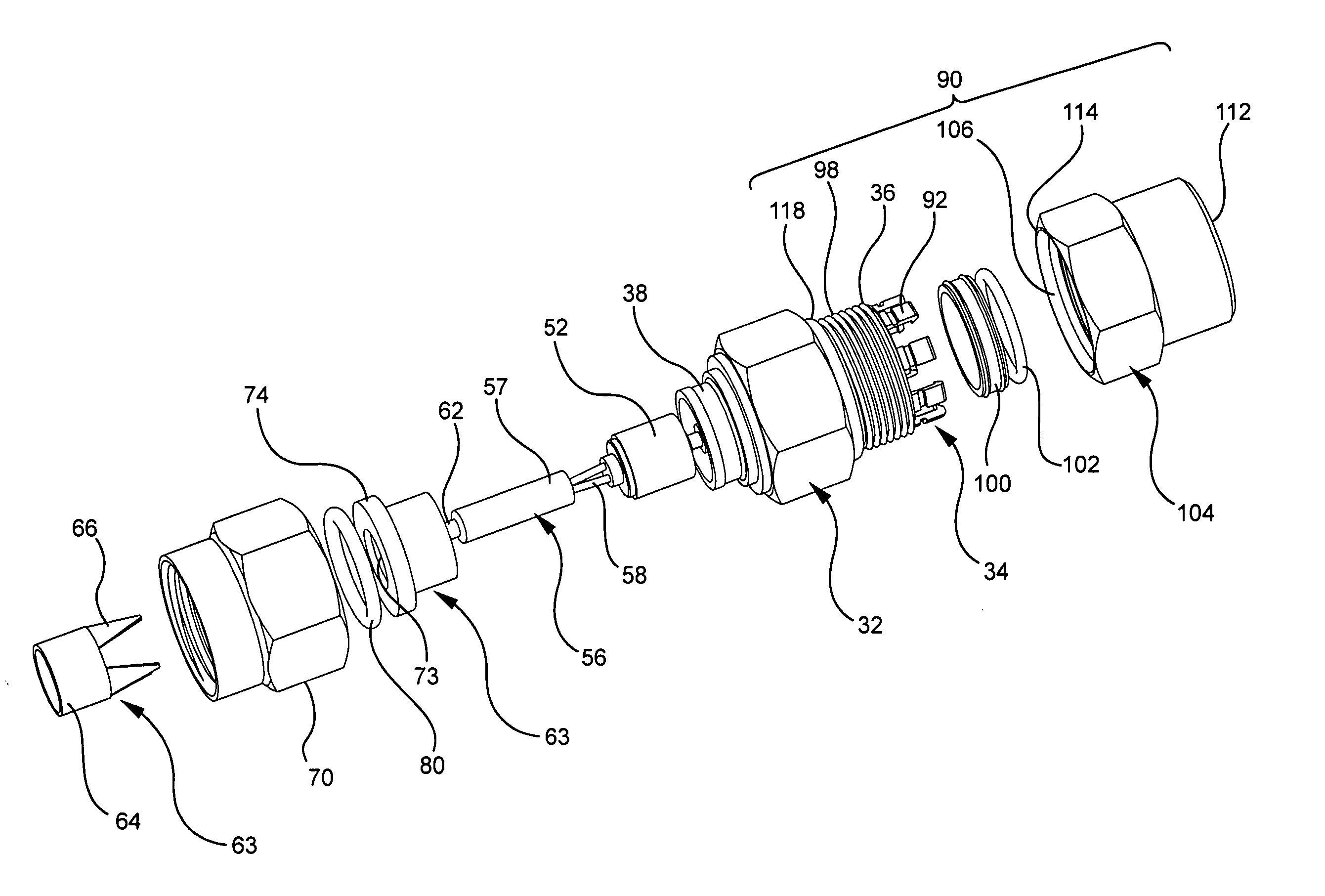
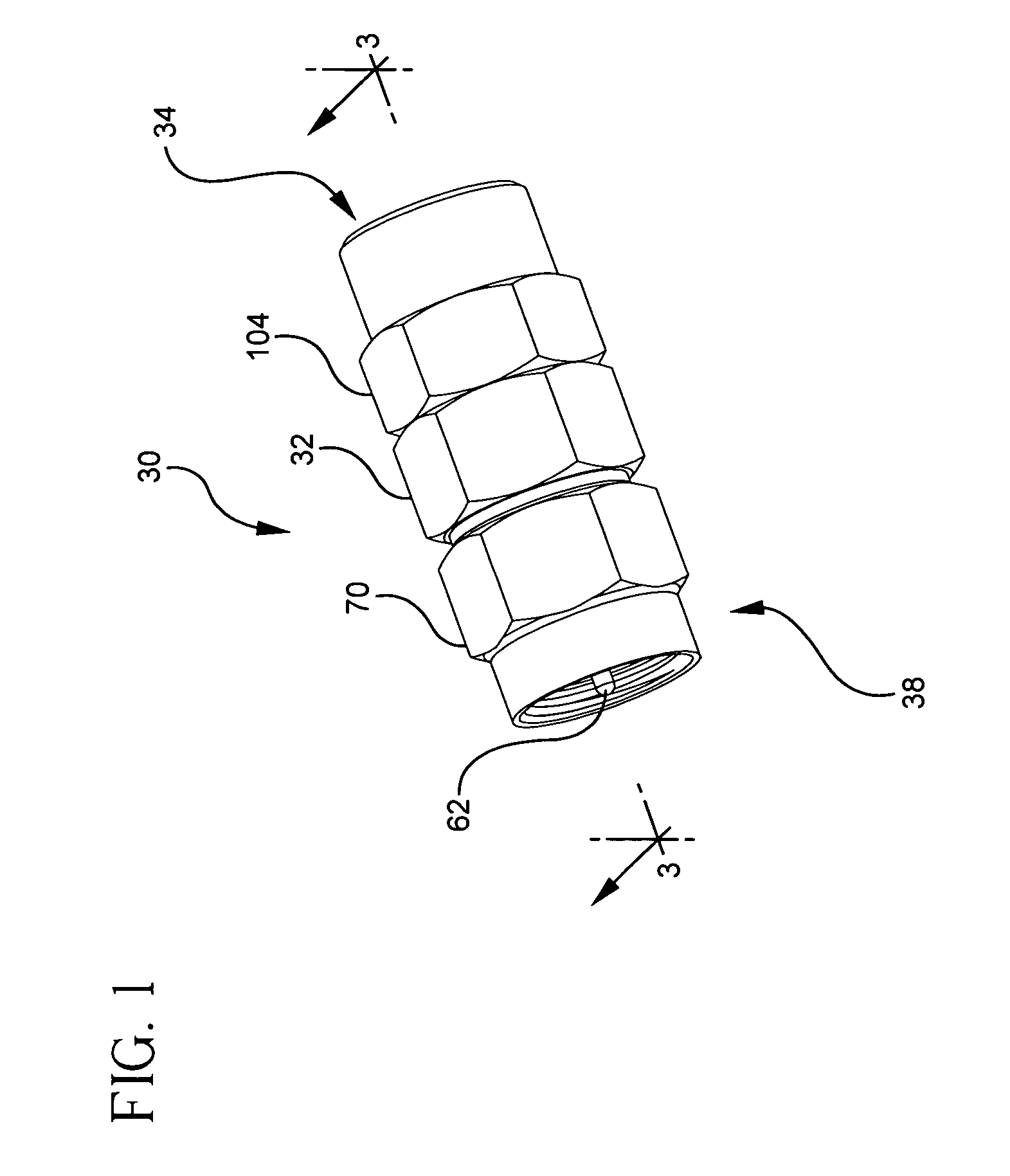
[0021] Referring to FIG. 1 a tooless coaxial connector 30 in accordance with the present invention is shown. The connector 30 has a housing 32 having a first end 34 and a lock ring 104 which accepts a cable (not shown). Positioned opposite the first end 34 is a second end 38 having a first nut 70 used to attach the connector 30 to the desired mating device (not shown). The connector 30 is shown fully assembled and is a compact design that does not require any specialized tools to attach either the mating device or the coaxial cable. The housing 32, first nut 70, and lock ring 104 can have a hexagonal outer profile to allow the use of a box wrench or open wrench to tighten the various parts of the connector 30.

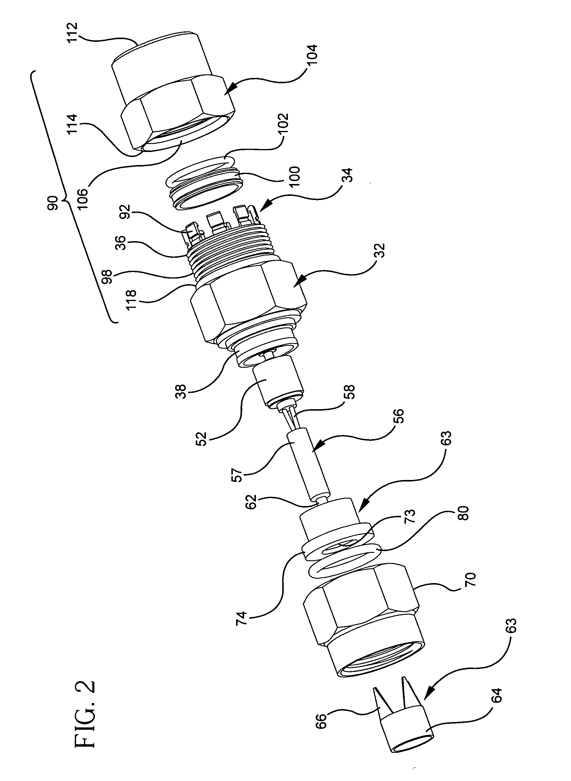
[0022] Referring to FIGS. 2 and 3 the connector 30 will be described in detail. A typical coaxial cable 10 is shown in FIG. 3. The cable 10 has a center conductor 12 having a dielectric covering 14 surrounding it. The dielectric layer 14 is covered by a foil 16 and a metallic ...


PUM


Abstract

The present invention is a tooless connector for mounting on a straight cut end of a coaxial shielded type cable. The connector can have a cylindrical housing with a first end for receiving the coaxial shielded cable and an oppositely positioned second end. A rear wall can be positioned in the interior of the cylindrical housing forming an abutment for the insertion of the coaxial cable. A terminal assembly including a ferrule assembly having at least one prong extending therefrom is positioned through the rear wall. The prong is positioned to contact a foil layer and/or a braided layer of the coaxial cable. A terminal extends through the center of the ferrule for receiving the center of the coaxial cable. A compression assembly is attached to the cylindrical housing to securely hold the coaxial cable after it has been inserted into the connector.

Description

CROSS-REFERENCE TO RELATED APPLICATIONS [0001] This application claims the benefit of U.S. Provisional Application No. 60 / 511,019 filed on Oct. 14, 2003 the disclosure of which is incorporated herein by reference.BACKGROUND OF THE INVENTION [0002] The present invention relates generally to a coaxial connector and more particularly to a tooless coaxial connector for a coaxial cable. [0003] Prior art coaxial connectors require a coaxial cable to be prepared by exposing the center conductor and the outer conductor. In addition, after the cable is inserted into the connector a special compression tool must be used to then attach the connector to the cable. [0004] Typical coaxial cables have a center conductor which is surrounded by a dielectric layer usually made of a foam material. Covering the dielectric layer is a metallic foil coating which is then surrounded by a metallic braid. The braid is then covered by an outer jacket made of an insulating material. A problem with current coax...

Claims


Application Information

Patent Timeline
Patent Type & Authority Applications(United States)
IPC IPC(8): H01R9/05
CPCH01R9/0521
Inventor RODRIGUES, JULIO F.
Owner BELDEN INC
Why Eureka
Try Eureka