Plug connector with external EMI shielding capability

a technology of shielding capability and plug connector, which is applied in the direction of coupling device details, coupling device connection, protective earth/shielding arrangement, etc., can solve the problems of high shielding cost, easy emi, and easy transmission of electromagnetic interference through the connector, and achieve the effect of expanding the grounding capability of the cable braid

Active Publication Date: 2013-05-14
MOLEX INC
View PDF115 Cites 44 Cited by
  • Summary
  • Abstract
  • Description
  • Claims
  • Application Information

AI Technical Summary

Benefits of technology

[0011]Yet a still further object of the Present Disclosure is to provide a plug connector in which the cable shielding braid is supported by the plug connector housing and is contacted by a clip member that provides an exterior point of contact on the plug connector housing which the exterior shielding collar encloses, the collar having a plurality of spring arms formed in opposition to the clip member so as the extend the grounding capability of the cable braid to a location proximate to the forward mating face of the plug connector to provide EMI shielding along the body of the plug connector housing.
[0014]The cable braid is extended over the premold portion and the free ends of the braid are preferably exposed in the connector housing portion that is molded over the internal premold portion so as to provide one or more conductive areas on the plug connector housing that are exposed for contact by an opposing member. Extending the cable braid in this manner extends the shielding from the cable directly to the body of the plug connector. A metal clip or a foil cover may be further applied over the braid to provide a smooth conductive area on the exterior surface of the connector housing.

Problems solved by technology

Electromagnetic interference (“EMI”) is prone to occur at the mating interface and along the body of such plug connectors and the shroud in which the plug connector is inserted has a loose fit around the exterior of the plug connector.
At high speeds, this interference may cause problems with the signals transmitted through the connector.
Shielding on the connector is one solution, but overall, such shielding is expensive and increases the cost of the plug connector.
One solution is to form a conductive exterior housing that supports the circuit card. however, this solution is expensive.

Method used


Image

  • Plug connector with external EMI shielding capability
  • Plug connector with external EMI shielding capability
  • Plug connector with external EMI shielding capability

Examples


Embodiment Construction

[0041]While the Present Disclosure may be susceptible to embodiment in different forms, there is shown in the Figures, and will be described herein in detail, specific embodiments, with the understanding that the disclosure is to be considered an exemplification of the principles of the Present Disclosure, and is not intended to limit the Present Disclosure to that as illustrated.

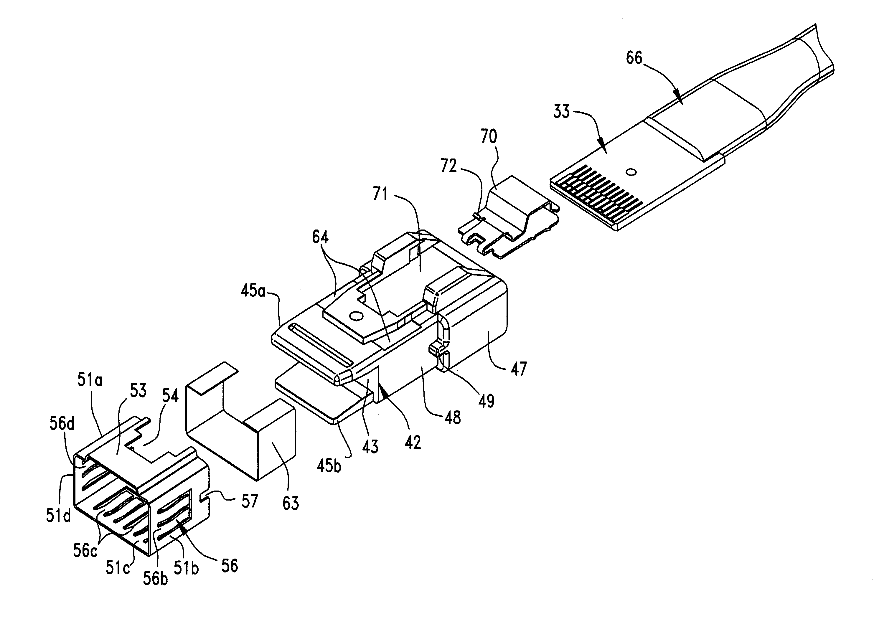
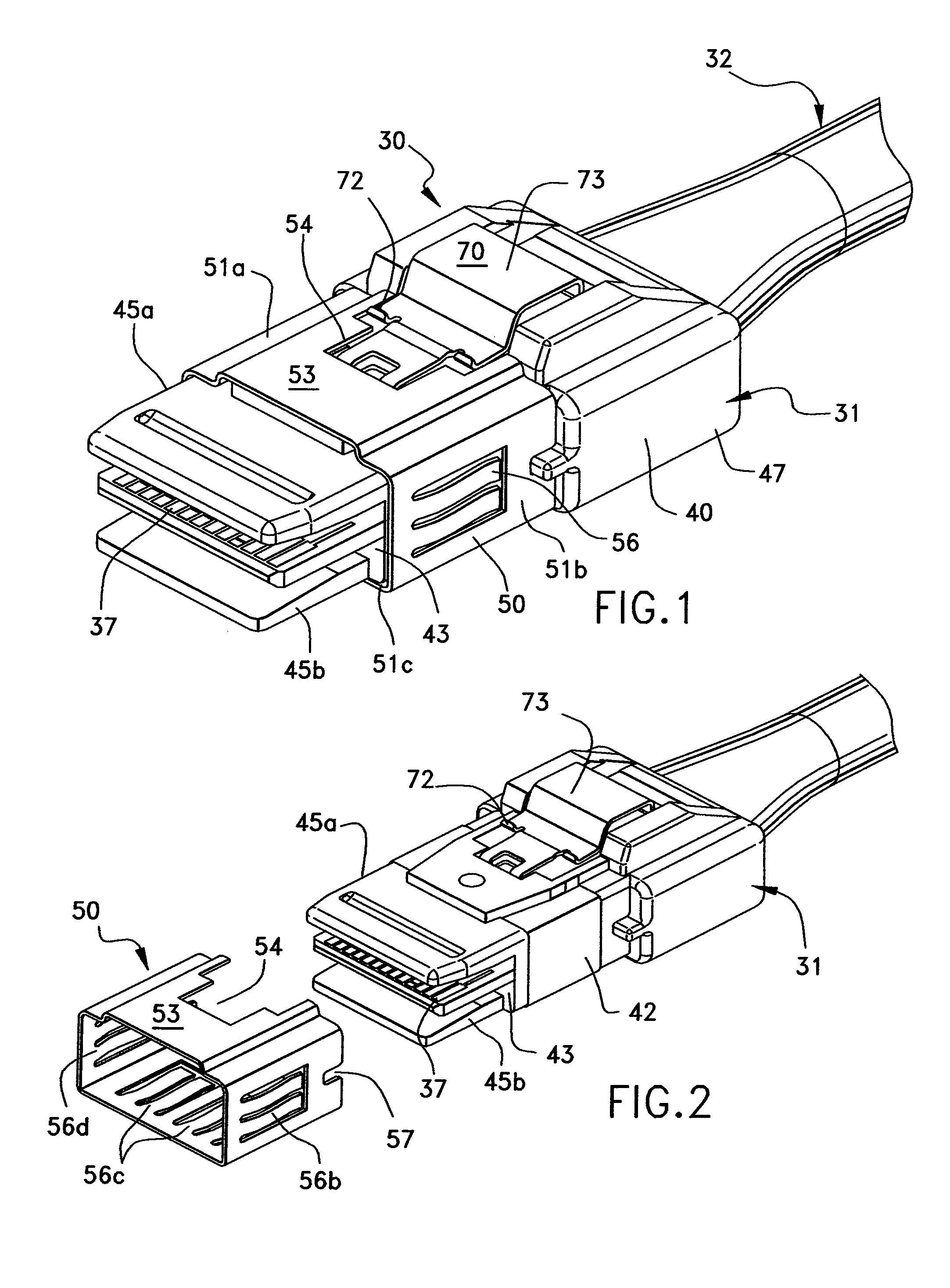
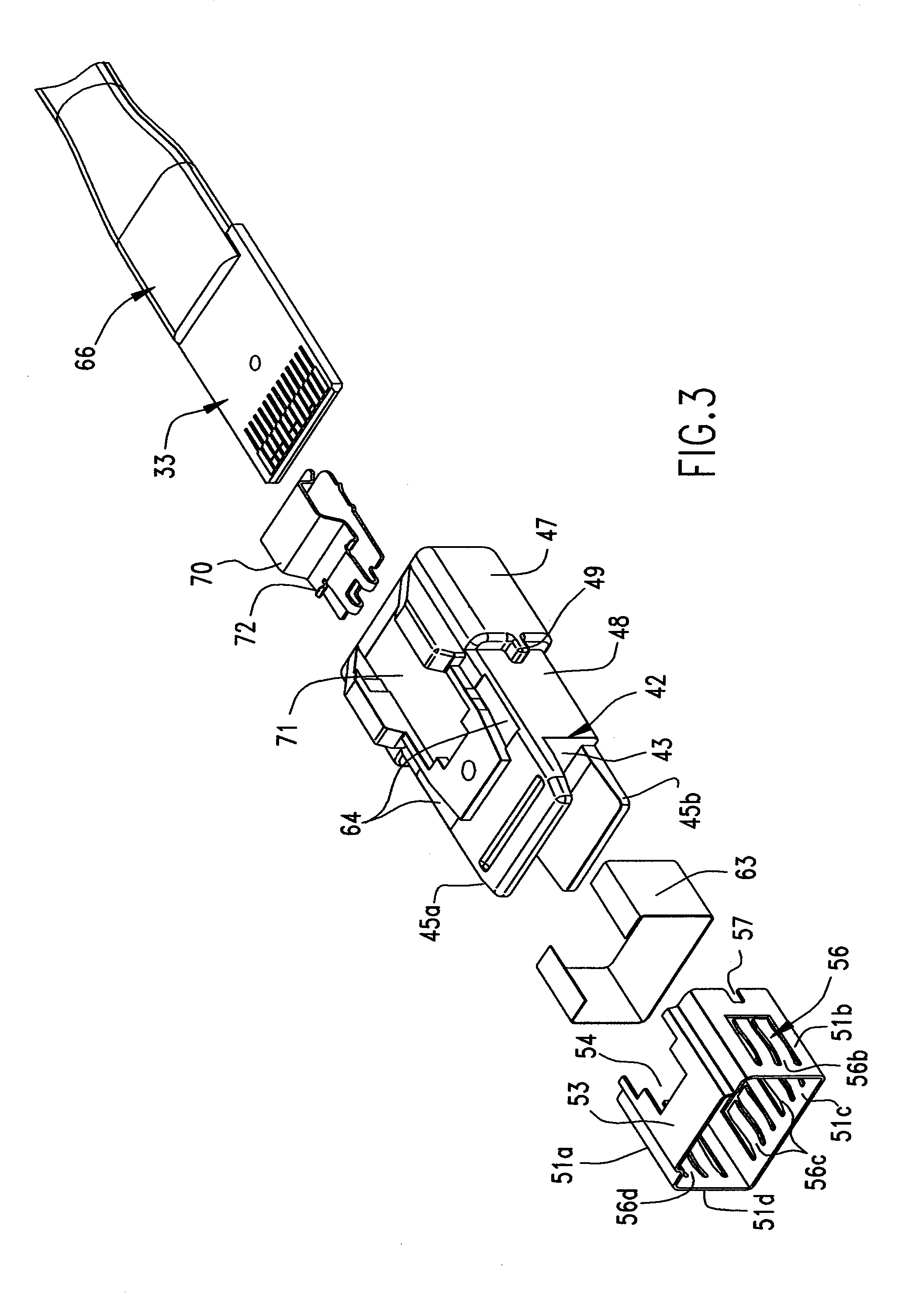
[0042]FIG. 1 is a perspective view of plug connector 30. Plug connector 30 is generally of the type that is disclosed in U.S. Pat. No. 7,303,438, issued 4 Dec. 2007 to the Assignee of the Present Disclosure, the contents of which is hereby incorporated by reference in its entirety. Such a plug connector may be utilized in internal applications where the plug and its cable provide a connection within an electronic device, such as, for example a router or server, or it may be utilized in an external application where the plug and cable are used to connect two electronic devices together. Plug connector 30 has...


PUM


Abstract

A shielded cable connector takes the form of a plug connector that is terminated to a plurality of wires of a cable. The wires are terminated to an edge card and a premold portion is formed thereover. An exterior shielding braid of the cable is extended over the premold and is formed with the connector housing so that a portion of it is exposed on the exterior of the connector housing. This exposed portion contacts an exterior conductive collar that is supported on the connector housing. The sleeve has a plurality of spring contact arms so as to make electrical shielding contact between the cable braid exposed on the connector housing and an exterior metal guide into which the connector is inserted when mating to an opposing connector.

Description

REFERENCE TO RELATED APPLICATIONS[0001]The Present Disclosure is a United States National Phase Application of PCT Patent Application No. PCT / US2010 / 0021465, entitled “Plug Connector With External EMI Shielding Capability,” filed on 20 Jan. 2010 with the U.S. Receiving Office of the Patent Cooperation Treaty. The Present Disclosure claims priority to U.S. Provisional Application No. 61 / 145,861, entitled “Plug Connector With External EMI Shielding Capability,” and filed 20 Jan. 2009, the contents of which is fully incorporated in its entirety herein.BACKGROUND OF THE PRESENT DISCLOSURE[0002]The Present Disclosure relates generally to plug connectors and more particularly to a plug connector with improved shielding.[0003]Plug connectors are well known in the art as connectors terminated most often to a cable containing a plurality of wires, and configured to mate with an opposing mating connector. These plug connectors, as shown in U.S. Pat. No. 7,303,438, issued 4 Dec. 2007, typicall...

Claims


Application Information

Patent Timeline
Patent Type & Authority Patents(United States)
IPC IPC(8): H01R13/648
CPCH01R13/65802H01R13/6582H01R13/658
Inventor SYTSMA, PETER H.SCHOESTER, BRADLEY C.DOYE, DENNIS LEE
Owner MOLEX INC
Why Eureka
Try Eureka