Noise suppressing structure for shielded cable

a shielded cable and noise suppression technology, applied in the direction of coupling protective earth/shielding arrangement, coupling device connection, aperture leaage reduction, etc., can solve the problems of increased cost, increased complexity of structure, increased mounting work, etc., to reduce the cost of connector, increase the cost, and increase the cost

Inactive Publication Date: 2004-10-05
NEC PLATFORMS LTD
View PDF6 Cites 41 Cited by
  • Summary
  • Abstract
  • Description
  • Claims
  • Application Information

AI Technical Summary

Benefits of technology

In such electromagnetic noise reducing structure, since the connector itself is not a special component but a general one, the cost may be reduced for the connector. However as for the shielding structural component, the structure increases in complexity, mounting work needs much time, and the cost is increased.
Consequently the connector is easily attachable and reliably shielded with a simple structure and the shielding sheath of the shielded cable is grounded at a low impedance though a general connector of non-shielded type is used to connect the shielded cable.

Problems solved by technology

However as for the shielding structural component, the structure increases in complexity, mounting work needs much time, and the cost is increased.

Method used


Image

  • Noise suppressing structure for shielded cable
  • Noise suppressing structure for shielded cable
  • Noise suppressing structure for shielded cable

Examples


Embodiment Construction

An embodiment of the present invention will be described with reference to the drawings.

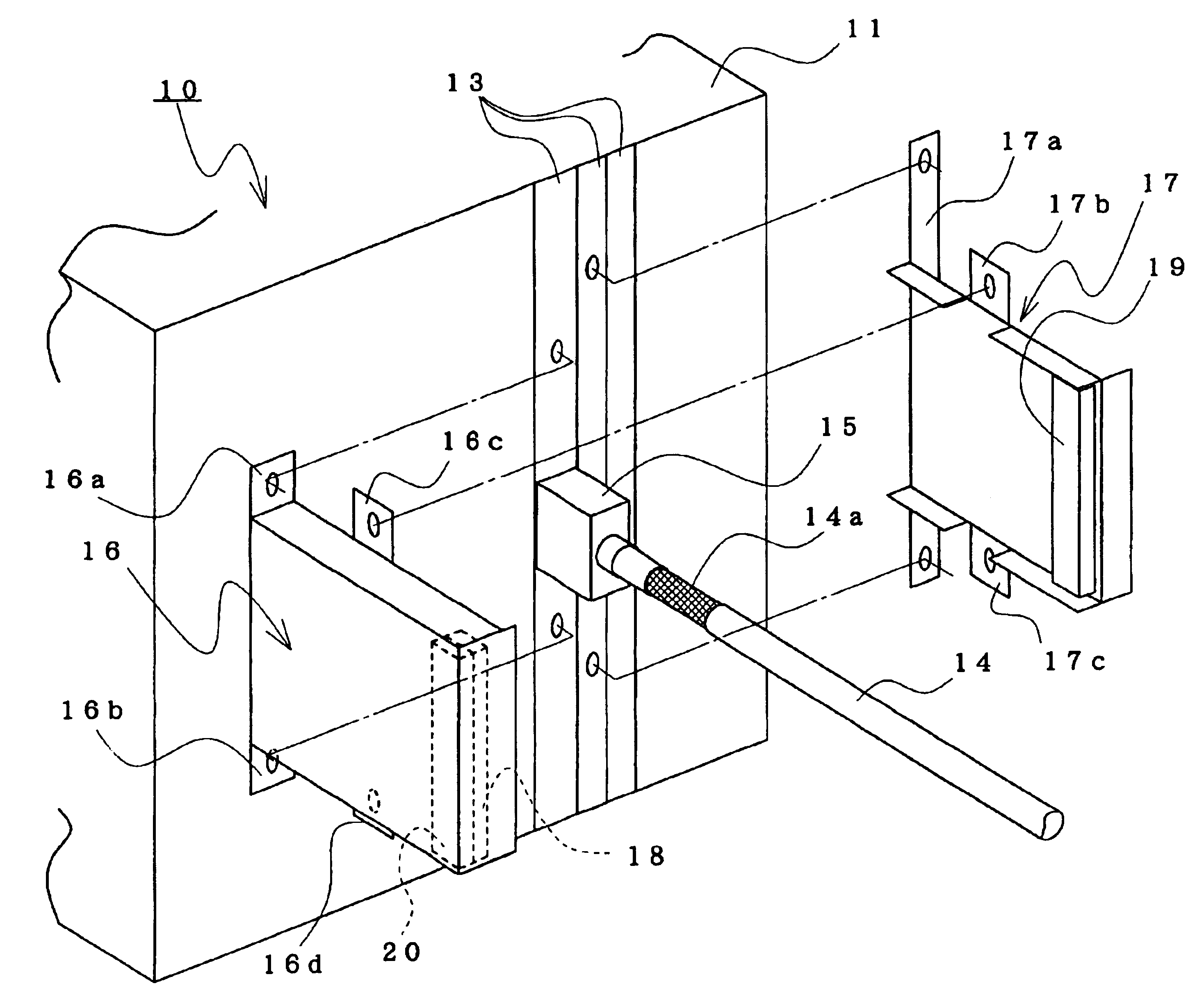
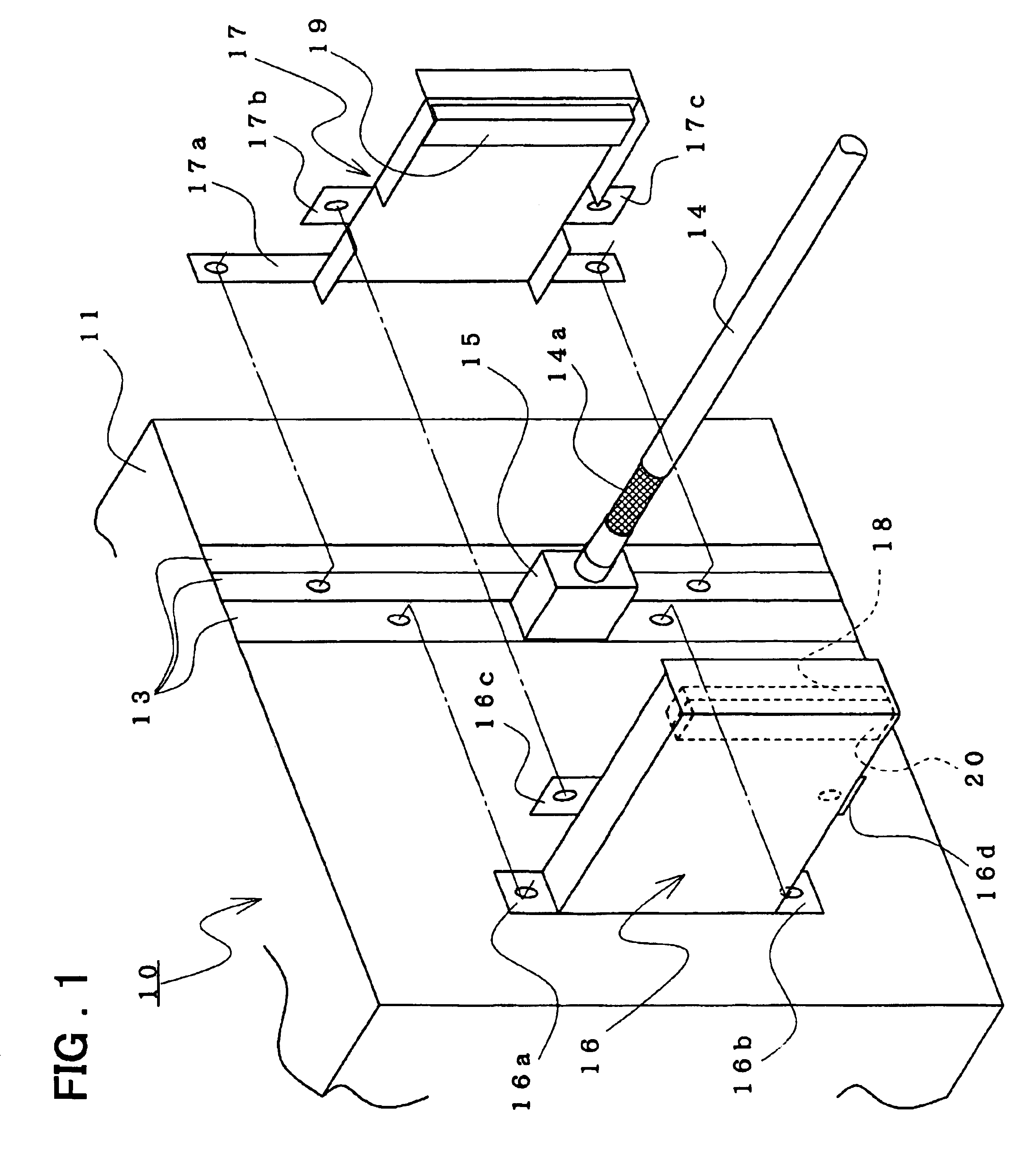
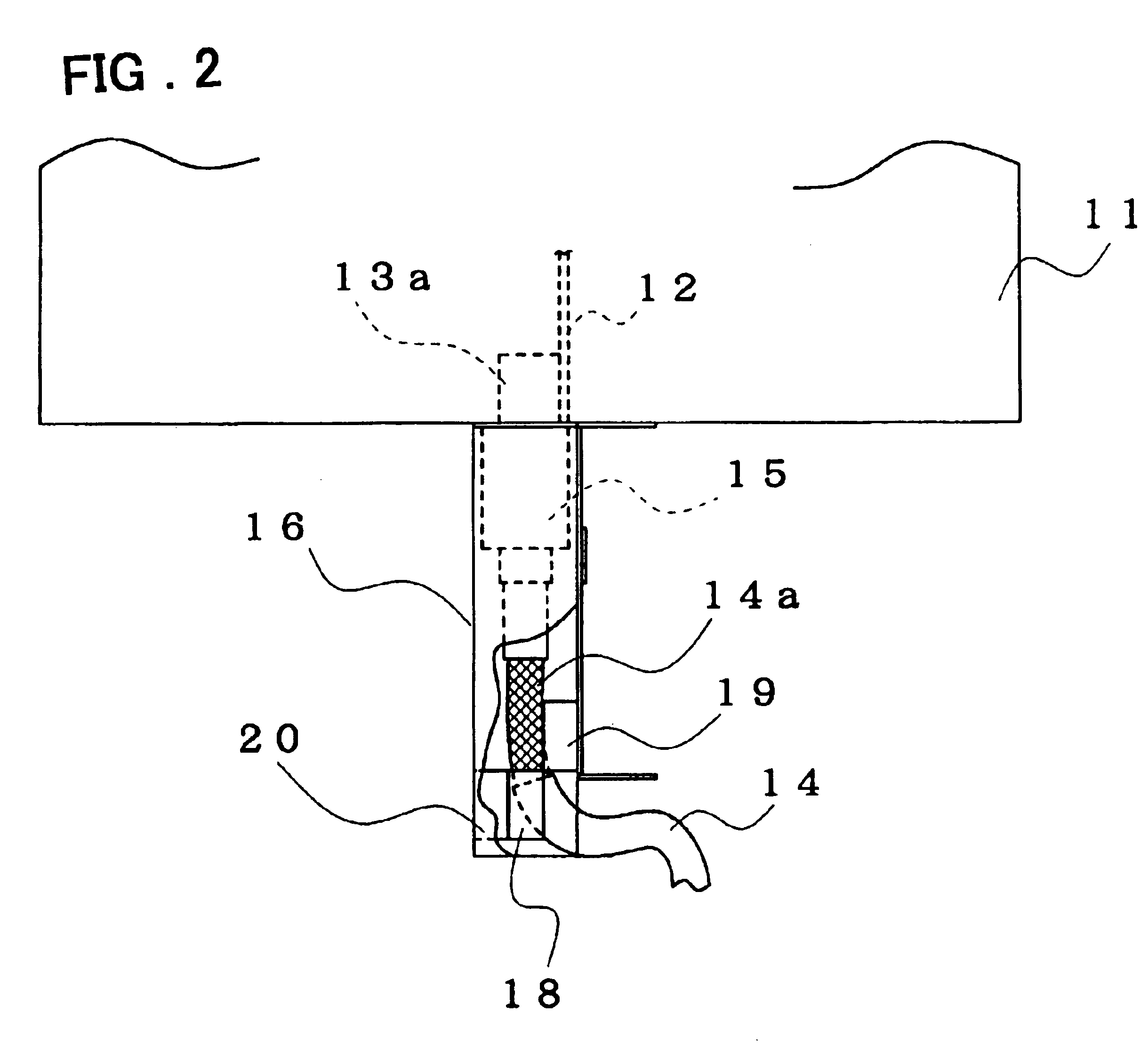
The embodiment of a noise suppressing structure for shielded cable of the present invention will be described with reference to FIGS. 1 and 2.

FIG. 1 is a block diagram showing a noise suppressing structure for shielded cable.

In FIG. 1, the noise suppressing structure 10 for shielded cable has a structure to be attached to a part of chassis 11.

Chassis 11 provides a circuit board 12 mounted on the chassis, and the circuit board 12 has a front plates 13 attached in the front of the circuit board as shown in FIG. 1. A connector 13a attached on the circuit board 12 is exposed to the exterior from an aperture of the front plate 13.

A connector 15 attached to a tip of a shielded cable 14 is connected to the connector 13a.

The circuit board 12 may be respectively attached to a plurality of mounting portions on the chassis 11. There are electronic parts and wiring patterns on the circuit board.

Front plates ...


PUM


Abstract

A low-cost noise suppressive technology using a general connector, reliably grounding to a shielding sheath of shielded cable at a low impedance by simple structure. The structure comprises conductive shielding covers attached to a chassis to enclose both sides of the second connector of non-shielded type at a tip of the shielded cable connected to the first connector mounted on the chassis and are fixed in a state to mate each other. Gaskets made of elastic material are respectively attached to inside of each shielding covers and made of conductive material being in electrical contact with the shielding cover. The gaskets are elastically contacted and conducted with the shielding sheath at an exposed portion of the shielded cable when the shielding covers are attached to the chassis to enclose the second connector and are fixed in the state to mate each other.

Description

The present invention relates to a noise suppressing structure for shielded cable, and in particular to a noise suppressing technology for shielded cable to ground a shielding sheath of the shielded cable.Conventionally it is widely known that shielded cable is used for connecting cable within a system to suppress the occurrence of EMI (electromagnetic interference) in all kinds of electronic equipment, particularly in communication equipment.The introduction of the shielded cable may very effectively suppress the occurrence of EMI. However in connecting to a circuit board within equipment and using a connector, it is unsatisfactory to ground a shielding sheath of the shielded cable or it is difficult to realize shielding of the connector itself.When the grounding of the shielding sheath or the shielding of the connector itself is insufficient like this, a radiative source of internal noise is introduced. When there is no grounding of a shielding sheath at a low impedance, for examp...

Claims


Application Information

Patent Timeline
Patent Type & Authority Patents(United States)
IPC IPC(8): H05K9/00H01R13/648
CPCH05K9/0018Y10S439/927
Inventor DEGUCHI, MASARU
Owner NEC PLATFORMS LTD
Why Eureka
Try Eureka