Dial structure
- Summary
- Abstract
- Description
- Claims
- Application Information
AI Technical Summary
Benefits of technology
Problems solved by technology
Method used
Image
Examples
first embodiment
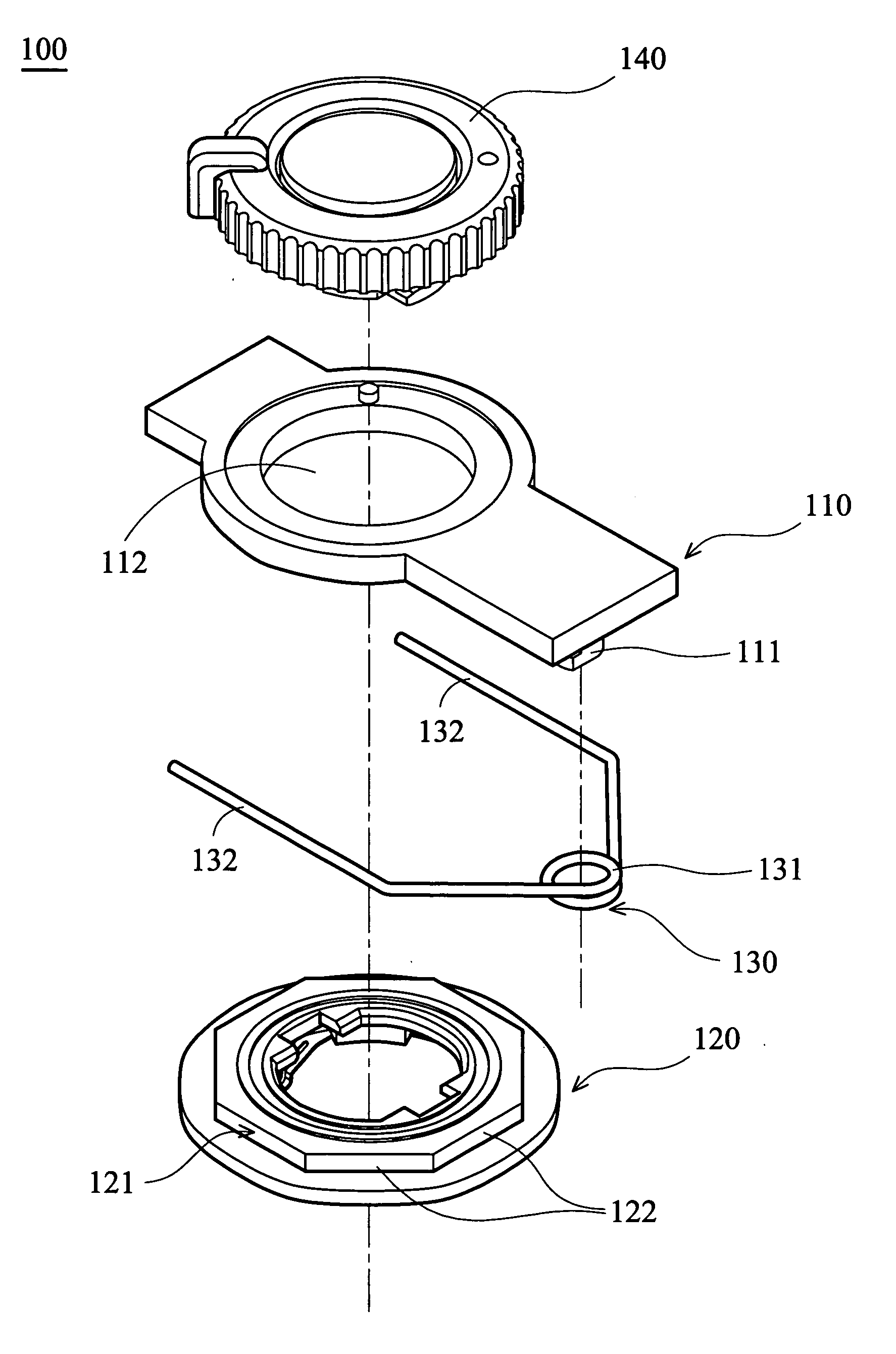
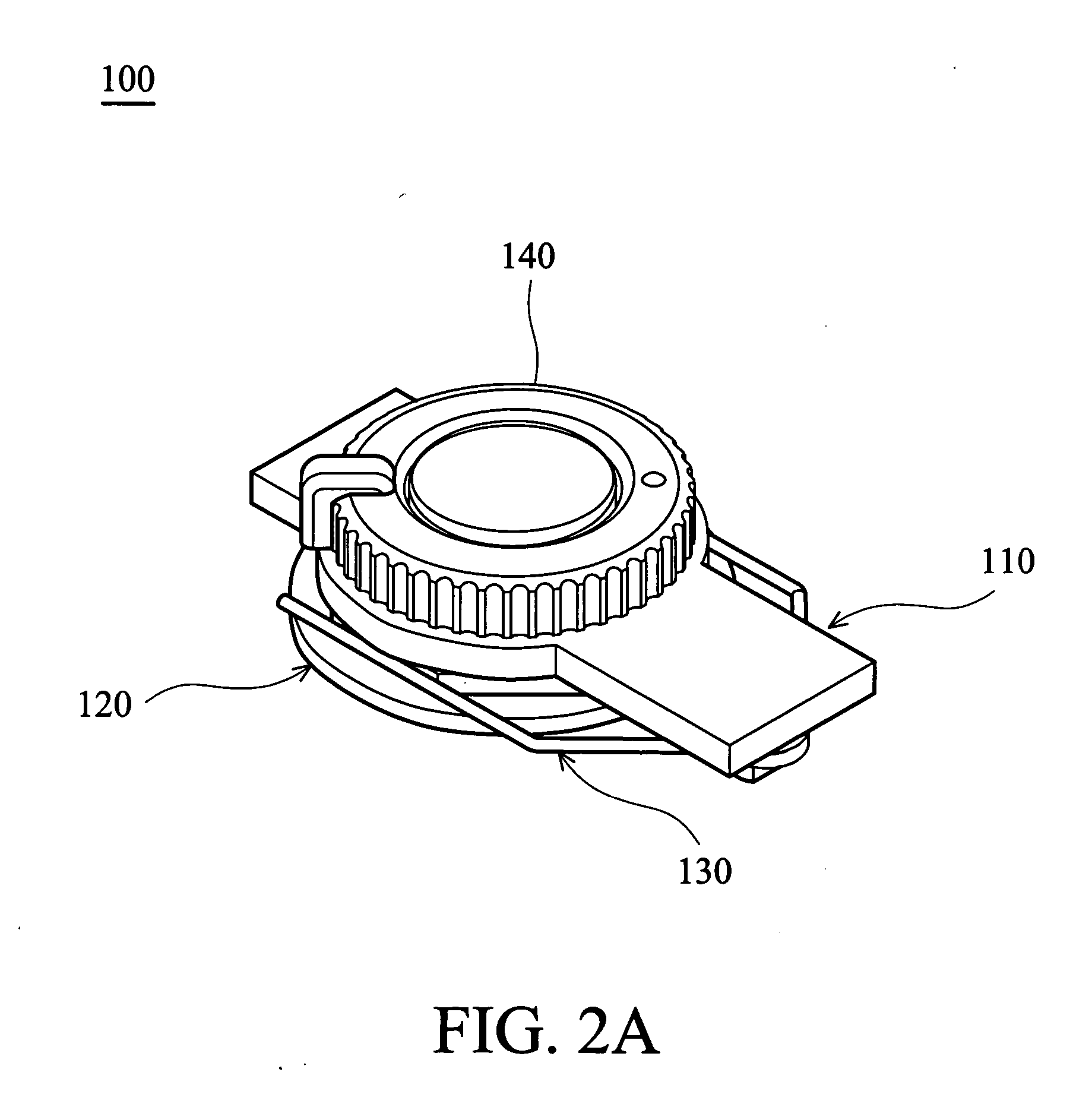
[0042] Referring to FIG. 3A, the annular contact surface 121 of the rotating member 120 is formed with a plurality of equidistant contact portions 122. Namely, the contact portions 122 form a regular polygonal annular contact surface 121. In this embodiment, the annular contact surface 121 is octagonal. In an initial condition, two first resilient arms 132 of the first resilient member 130 abut opposite contact portions 122 of the annular contact surface 121, respectively. At this point, the first resilient arms 132 provide predetermined resilience.
[0043] When the rotating member 120 rotates clockwise by a small angle, the first resilient arms 132 of the first resilient member 130 are spread by the annular contact surface 121 (contact portions 122), as shown in FIG. 3B. At this point, the annular contact surface 121 exerts a force F on each first resilient arm 132, thereby creating torque thereon. When the rotating member 120 continues to rotate clockwise, the distance between the ...
second embodiment
[0044] In this embodiment, elements corresponding to those in the first embodiment are given the same reference numerals.
[0045] Referring to FIG. 4, the annular contact surface 121′ of the rotating member 120 is formed with a plurality of equidistant teeth 122′. Namely, the contact portions 122 in the first embodiment are replaced by the teeth 122′. Specifically, the annular contact surface 121′ is formed with eight equidistant teeth 122′.
[0046] As shown in FIG. 4, in an initial condition, each first resilient arm 132 of the first resilient member 130 abuts the tops of two adjacent teeth 122′. At this point, each first resilient arm 132 provides predetermined resilience.
[0047] When the rotating member 120 (annular contact surface 121′) rotates, the first resilient arms 132 of the first resilient member 130 are spread by the tops of the teeth 122′. At this point, the top of each tooth 122′ exerts a force on each first resilient arm 132.
[0048] When the rotating member 120 continue...
third embodiment
[0049] In this embodiment, elements corresponding to those in the first and second embodiments are given the same reference numerals.
[0050] Referring to FIG. 5, the first resilient member of this embodiment is different from that of the second embodiment. Specifically, each first resilient arm 132 of the first resilient member 130′ has a curved portion 133. In an initial condition, the curved portion 133 of each first resilient arm 132 abuts the recess between two adjacent teeth 122′. At this point, each first resilient arm 132 provides predetermined resilience. Other elements in this embodiment are the same as those in the first and second embodiments, and explanation thereof will be omitted for simplification of the description.
[0051] When the rotating member 120 (annular contact surface 121′) rotates, the curved portions 133 of the first resilient arms 132 are spread by the tops of the teeth 122′. At this point, the top of each tooth 122′ exerts a force on each first resilient ...
PUM
 Abstract
Description
Claims
Application Information
 - R&D
- Intellectual Property
- Life Sciences
- Materials
- Tech Scout
- Unparalleled Data Quality
- Higher Quality Content
- 60% Fewer Hallucinations
Browse by: Latest US Patents, China's latest patents, Technical Efficacy Thesaurus, Application Domain, Technology Topic, Popular Technical Reports.
© 2025 PatSnap. All rights reserved.Legal|Privacy policy|Modern Slavery Act Transparency Statement|Sitemap|About US| Contact US: help@patsnap.com


