Transmission system

a transmission system and transmission mode technology, applied in data switching networks, time-division multiplexing selection, multiplex communication, etc., can solve the problems of communication itself, communication cannot be flexibly changed, and the vc operation mode setting is not easy, so as to improve the quality and reliability of communication

Inactive Publication Date: 2005-07-07
FUJITSU LTD
View PDF4 Cites 50 Cited by
  • Summary
  • Abstract
  • Description
  • Claims
  • Application Information

AI Technical Summary

Benefits of technology

[0016] The present invention was created in view of the above circumstances, and an object thereof is to provide a transmission system which is capable of flexibly setting and changing the VC operation mode and, in case of fault, can reset the VC mode to continue communication, thereby improving the quality and reliability of communication.

Problems solved by technology

Consequently, the VC operation mode setting is not easy, giving rise to a problem that the VC operation mode cannot be flexibly changed.
Also, a VC path is constituted by a plurality of STS paths to realize communication, but in conventional systems, if any of the paths constituting the VC path develops anomaly (fault), the communication itself becomes unavailable, posing a problem of low reliability.

Method used


Image

  • Transmission system
  • Transmission system
  • Transmission system

Examples


Embodiment Construction

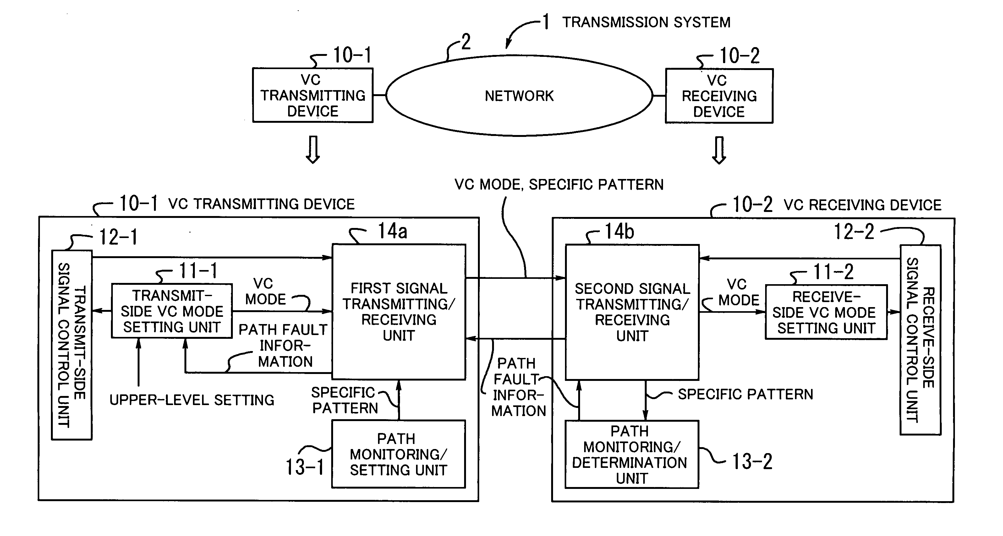
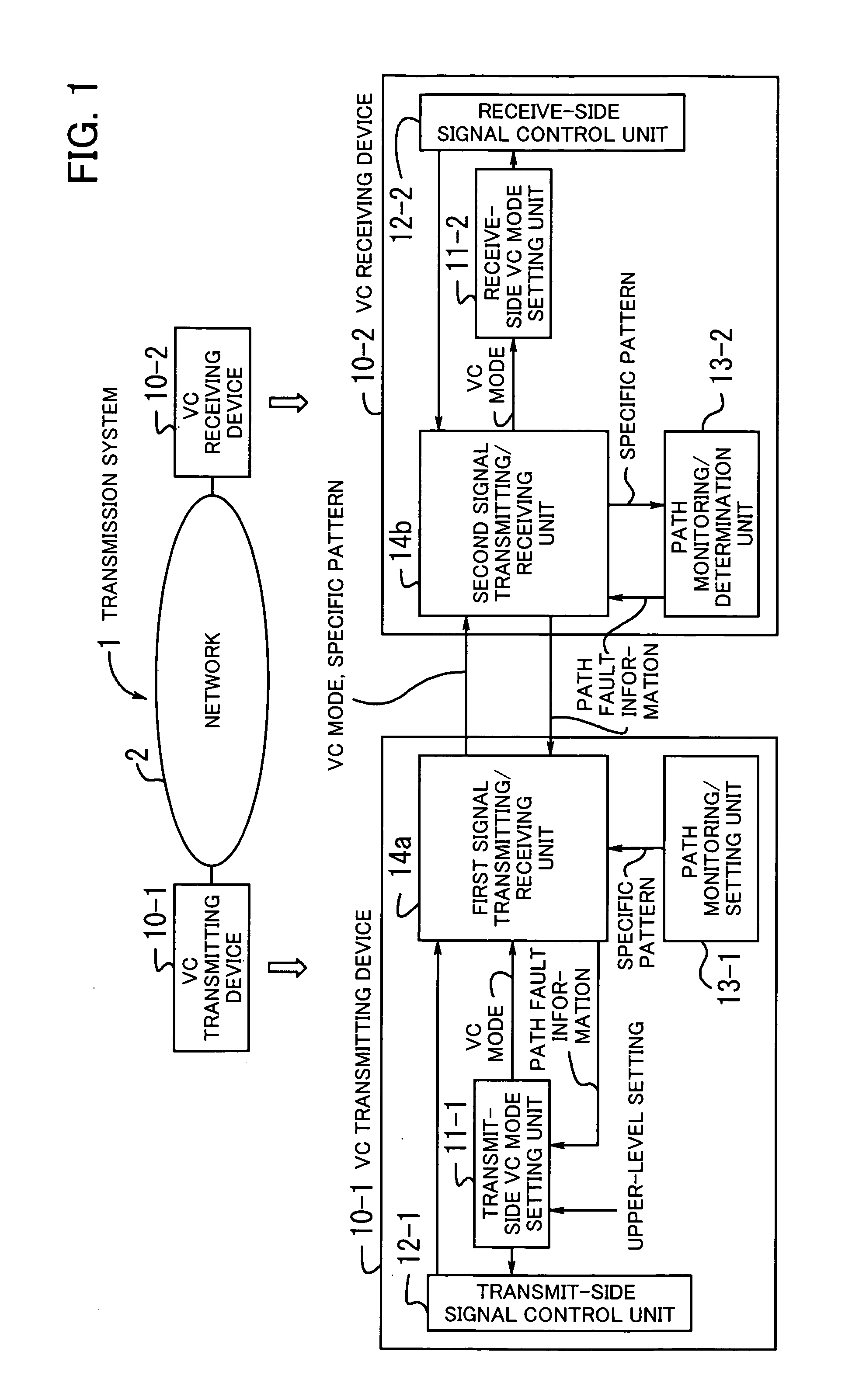
[0034] Preferred embodiments of the present invention will be described below with reference to the accompanying drawings. FIG. 1 illustrates the principle of a transmission system according to the present invention. The transmission system 1 comprises a VC transmitting device 10-1 and a VC receiving device 10-2 and carries out transmission control, over a network 2, for VC (Virtual Concatenation) in which bandwidth is handled as a set of virtual signal units (STS-1, STS-3c, etc.). In practice, the functions of the present invention performed by the VC transmitting and receiving devices 10-1 and 10-2 are incorporated into a single transmission device.

[0035] The VC transmitting device 10-1 includes a transmit-side VC mode setting unit 11-1, a transmit-side signal control unit 12-1, a path monitoring / setting unit 13-1, and a first signal transmitting / receiving unit 14a.

[0036] The transmit-side VC mode setting unit 11-1 sets a VC mode of the VC transmitting device 10-1 in accordance ...


PUM


Abstract

A transmission system which can flexibly set/change VC mode and, in case of fault, can reset the VC mode to continue communication. A transmit-side VC mode setting unit sets a VC mode according to upper-level setting or path fault information. A transmit-side signal control unit controls signals in the VC mode. A path monitoring/setting unit generates a specific pattern. A first signal transmitting/receiving unit transmits the VC mode and the specific pattern to a remote device, and receives path fault information from the remote device. A second signal transmitting/receiving unit detects the VC mode and the specific pattern and transmits path fault information to the remote device. A receive-side VC mode setting unit sets the received VC mode. A receive-side signal control unit controls signals in the VC mode. Based on the specific pattern, a path monitoring/determination unit generates the path fault information indicative of a path connection determination result.

Description

CROSS-REFERENCE TO RELATED APPLICATIONS [0001] This application is a continuing application, filed under 35 U.S.C. § 111(a), of International Application PCT / JP2002 / 009987, filed Sep. 26, 2002.BACKGROUND OF THE INVENTION [0002] (1) Field of the Invention [0003] The present invention relates to a transmission system, and more particularly, to a transmission system for carrying out transmission control for VC (Virtual Concatenation) in which bandwidth is handled as a set of virtual signal units. [0004] (2) Description of the Related Art [0005] SONET (Synchronous Optical Network) / SDH (Synchronous Digital Hierarchy), which is a core technology of multiplexing technologies, defines interfaces for efficiently multiplexing various communication services. The SONET / SDH technology is currently standardized and still on the way to development. [0006] Paths used in SONET networks are usually in the units STS (Synchronous Transport Signal)-1, STS-3c, STS-12c, STS-48c, etc. whose bandwidths are ...

Claims


Application Information

Patent Timeline
Patent Type & Authority Applications(United States)
IPC IPC(8): H04J3/14H04L12/28H04Q11/04
CPCH04J3/14H04J2203/0094H04J2203/006H04J2203/0042
Inventor SONODA, KAZUMASA
Owner FUJITSU LTD
Why Eureka
Try Eureka